
Datasheet
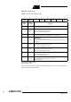

Table Of Contents
- Features
- Description
- Block Diagram
- SFR Mapping
- Pin Configurations
- Oscillators
- Enhanced Features
- Dual Data Pointer Register DPTR
- Expanded RAM (XRAM)
- Reset
- Power Monitor
- Timer 2
- Programmable Counter Array PCA
- Serial I/O Port
- Interrupt System
- Power Management
- Keyboard Interface
- 2-wire Interface (TWI)
- Serial Port Interface (SPI)
- Hardware Watchdog Timer
- ONCE(TM) Mode (ON Chip Emulation)
- Power-off Flag
- EEPROM Data Memory
- Reduced EMI Mode
- Flash Memory
- Electrical Characteristics
- Absolute Maximum Ratings
- DC Parameters
- AC Parameters
- Explanation of the AC Symbols
- External Program Memory Characteristics
- External Program Memory Read Cycle
- External Data Memory Characteristics
- External Data Memory Write Cycle
- External Data Memory Read Cycle
- Serial Port Timing - Shift Register Mode
- Shift Register Timing Waveforms
- External Clock Drive Waveforms
- AC Testing Input/Output Waveforms
- Float Waveforms
- Clock Waveforms
- Ordering Information
- Packaging Information
- Table of Contents
63
AT89C51ID2
4289C–8051–11/05
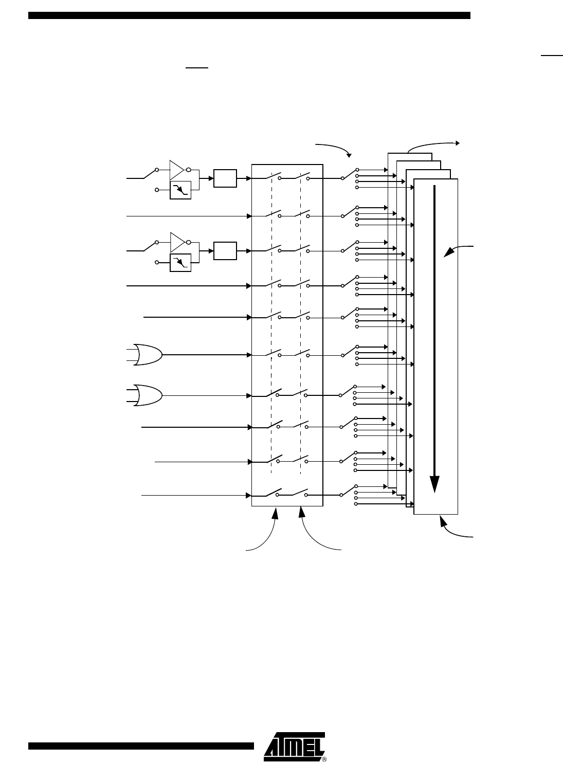
Interrupt System The AT89C51ID2 has a total of 10 interrupt vectors: two external interrupts (INT0 and
INT1
), three timer interrupts (timers 0, 1 and 2), the serial port interrupt, SPI interrupt,
Keyboard interrupt and the PCA global interrupt. These interrupts are shown in Figure
25.
Figure 25. Interrupt Control System
Each of the interrupt sources can be individually enabled or disabled by setting or clear-
ing a bit in the Interrupt Enable register (Table 52 and Table 50). This register also
contains a global disable bit, which must be cleared to disable all interrupts at once.
Each interrupt source can also be individually programmed to one out of four priority lev-
els by setting or clearing a bit in the Interrupt Priority register (Table 53) and in the
Interrupt Priority High register (Table 51 and Table 52) shows the bit values and priority
levels associated with each combination.
IE1
0
3
High priority
interrupt
Interrupt
polling
sequence, decreasing from
high to low priority
Low priority
interrupt
Global Disable
Individual Enable
EXF2
TF2
TI
RI
TF0
INT0
INT1
TF1
IPH, IPL
IE0
0
3
0
3
0
3
0
3
0
3
0
3
PCA IT
KBD IT
SPI IT
0
3
0
3
0
3
TWI IT