
User manual

30
Atmel AVR32025
32150B-AVR-03/12
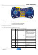
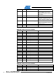
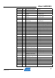
QFP48 Pin GPIO GPIO alternate functions Feature
23 PB10
GPIO[42] / GLOC.OUT[1] /
PWAM[33]
LED_1
44 PB11 CAT.VDIVEN CAT-VDIVEN
5 PB12 CAT.CSA[15] TOUCH_Y7
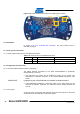
NOTE Some pins offer multiple GPIO alternate function configuration, while others don’t. For
example, for LED1 (PB10), it is possible to drive the intensity of the LED through a
regular GPIO function or through the PWMA function multiplexed on this pin.
However, for TOUCH_Y7 (PB12), if the GPIO function configuration is different than
CAT.CSA[15], the touch interface of this board won’t be functional.
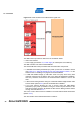
3.8.4 Configuration and test points
3.8.4.1 Config
uration
A UART boot loader is pre-loaded on the Atmel AT32UC3L064. To enter this boot
loader mode, the WAKE pushbutton must be pressed upon reset and then released.
It is then possible to program the AT32UC3L064 through the UART boot loader. Note
also that if the Atmel AT32UC3B1256 is running the pre-loaded virtual com port
firmware, it is possible to program the AT32UC3L064 with the UART boot loader
through the USB. For detailed information on the AVR UC3 UART boot loader, see
Section 2.4.6.
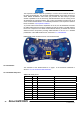
3.8.4.2 Test point
s
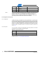
A few test points covering the AT32UC3L064 have been placed on the Atmel
AT32UC3L-EK for the verification of important signals.
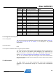
Table 3-21. AT32UC3L064 test points.
Designation Feature
TP3 GNDANA
TP5 GND
TP6 VDDANA
To locate the test points mentioned here above, use the assembly top/bottom views
provided in Section 2.4.2, The AT32UC3L-EK schematics.