
User manual

28
Atmel AVR32025
32150B-AVR-03/12
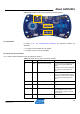
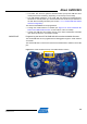
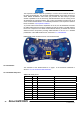
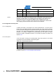
The expansion interface offers the possibility to connect various external devices to
the Atmel AT32UC3L064. The J8 header (labeled WLESS on the PCB) connects an
Atmel RZ600 AT86RF231 radio board (not provided with this board) to provide
wireless capabilities to the kit. Obviously, dedicated firmware must be running on the
AT32UC3L064 to support this feature. The J14 and J15 headers provide access to all
of the AT32UC3L064’s GPIOs. For a detailed presentation of the expansion interface
block, see Section 3.6, Expansion interface.
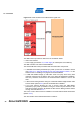
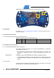
To provide
USB communication capabilities to the kit, the AT32UC3L064 accesses
the USB interface block through the USART3 RX and TX signals. The USB interface
block main component is the Atmel AT32UC3B1256 device, pre-loaded with several
default firmware components providing added features to the kit. For a detailed
presentation of the USB interface block, see Section 3.7, USB interface.
Figure 3-19. Atmel AT32UC3L
-EK top view AT32UC3L064.
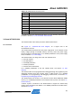
3.8.2 Schematics
The
schematic of the AT32UC3L064 is on page 1 in the document mentioned in
Section 2.4.2, The AT32UC3L-EK schematics.
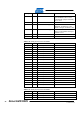
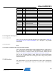
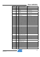
3.8.3 AT32UC3L064 pinout
Table 3-20. UC3L pin
out.
QFP48 Pin GPIO GPIO alternate functions Feature
33 N.A. N.A. GNDANA
34 N.A. N.A. ADVREFP
1 N.A. N.A. GND
19 N.A. N.A. GND
43 N.A. N.A. GND
45 N.A. N.A. GND
22 N.A. N.A. RESET_N
35 N.A. N.A. VDDANA
17 N.A. N.A. VDDIN
18 N.A. N.A. VDDCORE