
User manual

Atmel AVR32025
27
32150B-AVR-03/12
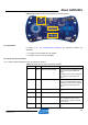
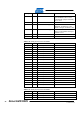
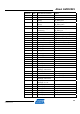
Table 3-19. USB interface block test points.
Designation Feature
TP31 VBUS
TP32 D-
TP33 D+
TP34 GND
TP35 JTAG.TCK.UC3B
TP36 JTAG.TDO.UC3B
TP37 JTAG.TMS.UC3B
TP38 JTAG.TDI.UC3B
TP39 RESET_N.UC3B
TP41 USB MODE pushbutton state
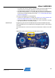
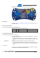
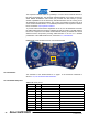
To locate the test points mentioned here above, use the assembly top/bottom views
provided in Section 2.4.2, The AT32UC3L-EK schematics.
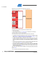
3.8 Atmel AT32UC3L064
The AT32UC3L064 is the central point of the Atmel AT32UC3L-EK.
3.8.1 Overview
See Figure 2-1. AT32UC3L-EK block diagram., for a lo
gical view of the
AT32UC3L064 in the kit.
The AT32UC3L064 is powered from the power supply block. It can read the current
battery voltage (through an ADCIFB channel), and may control the power supply
block through the Power-Off signal. For a detailed presentation of the power supply
block, see Section 3.1, Power supply.
The AT32
UC3L064 is in charge of the main user interface block:
• The touch sensors
• The LEDs LED0-4
• The WAKE pushbutton
• The RST pushbutton
• The three-axis accelerometer
For a detailed presentation of the user interface block, see Section 3.2, User
interface.
The AT
32UC3L064 can be programmed and debugged through the programming and
debugging interface block that provides JTAG or aWire access. For a detailed
presentation of the programming and debugging interface block, see Section 3.3,
Programming and debugging interface.
The AT32
UC3L064 has access to one external on-board Atmel DataFlash 64Mbit
memory. For a detailed presentation of the external memory block, see Section 3.4,
External memory.
A 32kHz
crystal is connected to the AT32UC3L064 to support the lowest sleep
modes, and to provide the RTC feature. For a detailed presentation of the RTC block,
see Section 3.5, RTC.