
User manual

26
Atmel AVR32025
32150B-AVR-03/12
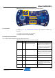
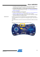
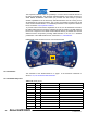
Figure 3-18. Atmel AT32UC3L-EK bottom view USB interface location.
3.7.2 Schematics
In Sec
tion 2.4.2, The AT32UC3L-EK schematics, the
USB interface block is
described on page 6.
3.7.3 UC3L-specific information
3.7.3.1 Atm
el T32UC3L064 pinout for the USB interface block
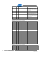
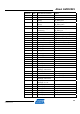
Table 3-18. UC3L pinout for the USB interface block.
QFP48 pin GPIO GPIO alternate functions Feature
6 PB00 USART3.TXD USART3 TX line
16 PB01 USART3.RXD USART3 RX line
3.7.4 Configuration and test points
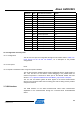
3.7.4.1 AT32UC3LB1256 default firmware configuration
The default firmware pre-loaded on the Atmel AT32UC3B1256 is dynamically
configurable upon power up:
• The USB DFU boot loader can be enabled by closing the J12 jumper. Use
flip/batchisp to read/write resources on the AT32UC3B1256 through the boot
loader
IMPORTANT Programming the AT32UC3B1256 will overwrite the default firmware.
• If the USB MODE pushbutton is pressed at power up, the USB virtual com port
firmware will execute. Otherwise, the USB HID QTouch Debug firmware will
execute
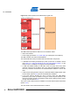
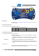
3.7.4.2 Test points
A few test points covering the USB interface block have been placed on the Atmel
AT32UC3L-EK for the verification of important signals.
J13
UC3B