
User manual

24
Atmel AVR32025
32150B-AVR-03/12
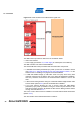
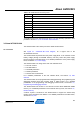
3.7.1 Overview
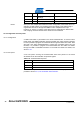
Figure 3-16. Atmel AT32UC3L-EK USB interface logical view.
The USB interface provides two features to the AT32UC3L-EK kit:
• USB communication
• Power supply (see Section 3.1, Power supply for a descriptio
n of that feature)
The USB controller is the Atmel AT32UC3B1256.
The AT32UC3B1256 comes pre-loaded with several firmware components:
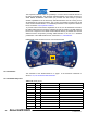
• A USB DFU boot loader [accessible upon power up when the J12 header is closed
(see Figure 3-17. Atmel AT32UC3L-EK top view USB interface location., for the
locatio
n of the J12 header)] to re-program the AT32UC3B1256
• A USB CDC-USART bridge (a USB CDC virtual com port) where every data
character received from the USB is sent to the Atmel AT32UC3L064’s USART3,
and every character received from the AT32UC3L064’s USART3 is sent to the
USB
• A HID QTouch Debug firmware acting as a USB HID-USART bridge between AVR
QTouch Studio (Section 2.4.8) and the
AT32UC3L064’s USART3
• A tiny boot selector allowing the user to choose (using the USB MODE
pushbutton) upon power up between running the virtual com port firmware or the
HID QTouch Debug firmware. By default the HID QTouch Debug firmware will be
running. See also Section 2.4.3
The so
urce code of this firmware is available in the Atmel AVR Software Framework
(Section 2.4.5).
The user inte
rface of the USB interface block is made of: