
User manual

Atmel AVR32025
23
32150B-AVR-03/12
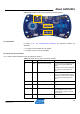
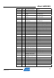
QFP48 pin GPIO GPIO alternate functions Feature
24 PA21 Software-dependant J15.7
9 PA22 Software-dependant J15.9
6 PB00 Software-dependant J15.11
16 PB01 Software-dependant J15.13
7 PB02 Software-dependant J15.15
8 PB03 Software-dependant J15.17
- - - GND on J15.19
- - - VCC3 on J15.2
21 PB04 Software-dependant J15.4
20 PB05 Software-dependant J15.6
30 PB06 Software-dependant J15.8
31 PB07 Software-dependant J15.10
32 PB08 Software-dependant J15.12
29 PB09 Software-dependant J15.14
23 PB10 Software-dependant J15.16
44 PB11 Software-dependant J15.18
5 PB12 Software-dependant J15.20
3.6.4 Configuration and test points
3.6.4.1 Configuration
The J8.1 and J8.2 pins are configurable through the J44 header. Refer to Table 3-15.
UC3L pino
uts for the J8 and J44 headers., for a description of the possible
configurations.
3.6.4.2 Test points
None.
3.6.4.3 Special consideration when using the expansion headers
The J8+J44 expansion headers gather signals multiplexed with the JTAG signals on
J8.1, J8.2, and J8.5. For this reason, JTAG debugging is not possible when an
external component is connected to these pins of the WLESS header. See also
Section 3.3.4.1, Special considerations for the RESET_N pin and the JTAG pins.
The J14 a
nd J15 headers gather all GPIO signals of the Atmel AT32UC3L064.
Obvious care should be taken when accessing pins that are being used by another
component of the kit.
3.7 USB interface
The USB interface on the Atmel AT32UC3L-EK offers USB communication
capabilities to the AT32UC3L064 through the on-board Atmel AT32UC3B1256
device.