
User manual

Atmel AVR32025
13
32150B-AVR-03/12
3.2.4 Configuration and test points
3.2.4.1 Hardware configuration
The default hardware configuration of the user interface block implies that:
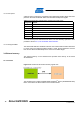
• There is no hardware to support debounce on the RST pushbutton: R36 is not
mounted, so C4 has no effect. This was done to support the aWire programming
and debugging interface (refer to Section 3.3 Programming and debugging
interface)
To en
able the hardware debounce support on the RST pushbutton, mount the 0Ω
R36 resistor (solder patch).
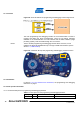
To locate the R36 resistor mentioned here above, use the assembly top/bottom views
provided in Section 2.4.2, The AT32UC3L-EK schematics.
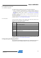
3.2.4.2 Test point
s
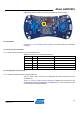
A few test points covering the user interface block have been placed on the
AT32UC3L-EK for the verification of important signals.
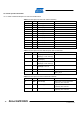
Table 3-6. User interface block test points.
Designation Feature
TP1
Input voltage on the Atmel AT32UC3L064 RESET_N pin, depending on the
state of the RST pushbutton
TP18 Input voltage for the accelerometer. Should be 1.8V nominal
TP15 Output voltage on the accelerometer VoutZ pin
TP16 Output voltage on the accelerometer VoutY pin
TP17 Output voltage on the accelerometer VoutX pin
TP19
Input voltage on the AT32UC3L064 WAKE_N pin, depending on the state of
the WAKE pushbutton
TP20 Voltage level on LED0
TP21 Voltage level on LED1
TP22 Voltage level on LED2
TP23 Voltage level on LED3
To locate the test points mentioned here above, use the assembly top/bottom views
provided in Section 2.4.2, The AT32UC3L-EK schematics.
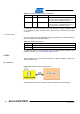
3.3 Programming and debugging interface
The programming and debugging interface block of the AT32UC3L-EK provides the
developer with a means to debug an application running on the AT32UC3L064.