
User manual

6
AVR32907
32137A-AVR-10/10
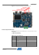
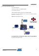
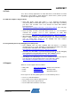
Figure 2-5. Graphical user interface
The GUI is composed of four items:
• Potentiometer and microphone
The potentiometer and the microphone are connected to ADC channels. The
potentiometer and microphone values are displayed in the potentiometer and
microphone boxes, respectively.
• CAN
The potentiometer value is sent via the CAN bus through CAN Node 1 and is
received by CAN Node 2. The message content is displayed in the CAN box.
• LIN
The LIN message built from CAN Node 2 is sent on the LIN bus through LIN Node
1 and received by LIN Node 2. The content of this LIN message received by LIN
Node 2 is displayed in the LIN box.
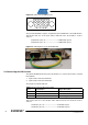
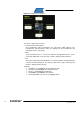
Touching:
o the RIGHT (>) pad highlights the potentiometer item
o the LEFT (<) pad highlights the microphone item
o the UP (^) pad highlights the CAN item
o the DOWN (v) pad highlights the LIN item
o the PLAY/PAUSE (>/||) focuses the highlighted item