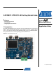
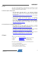
AVR32907: AT32UC3C-EK Getting Started Guide Features • Powering up the board • Block diagram • Using the preloaded firmware 1 Introduction 32-bit Microcontrollers Application Note The Atmel® AT32UC3C-EK is a reference design and development system for the Atmel® AVR® 32-bit AT32UC3C0512C microcontroller. The kit is equipped with a rich set of peripherals that make the AT32UC3C-EK a perfect evaluation platform. This guide shows the user how to quickly get started with this kit. Figure 1-1.
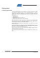
Getting started 2.1 Powering up the board The Atmel AT32UC3C-EK offers four interfaces to power the board: from the USB virtual COM port (USB VCP) interface, from the USB USER interface, or from an external source connected to either the J1 or J2 header. If two power sources are applied at the same time, the following priorities are used to select the current valid power source: 1. 2. 3. 4.
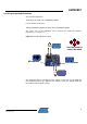
AVR32907 Figure 2-1. Possible power input interfaces on the AT32UC3C-EK (J27) USB VCP (J21) USB User (J1) Power Supply Jack (J2) Power Supply 2-pin header 2.2 Connecting the CAN interface The Atmel AT32UC3C-EK offers two CAN interfaces to connect the board to external CAN networks: 1. DB9 connector CAN Node 1 2. DB9 connector CAN Node 2 Table 2-1.
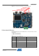
Figure 2-2. CAN connector DB9 pin-out 1 2 6 3 7 4 5 8 9 The preloaded firmware requires a loopback between CAN Node 1 and CAN Node 2. That means that one of the 2-pin cables delivered in the kit should be used to connect: CAN Node 1 pin 2 Å-------------------------Æ CAN Node 2 pin 2 CAN Node 1 pin 7 Å-------------------------Æ CAN Node 2 pin 7 Figure 2-3. CAN loopback on the AT32UC3C-EK 2.
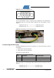
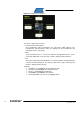
AVR32907 2.4 Using the preloaded firmware The preloaded application, AT32UC3C_EK_CAN_LIN_LOOPBACKS_DEMO is located under the directory, APPLICATIONS/AT32UC3C_EK_CAN_LIN_LOOPBACKS_DEMO The source code of the application can be found in the AVR UC3 Software Framework (see section 4.3). Figure 2-4. Default application running CAN Use the arrow to select the menu Microphone Potentiometer LIN This application gathers potentiometer data, displays it, and sends it to the CAN and LIN loopback interfaces.
Figure 2-5. Graphical user interface The GUI is composed of four items: • Potentiometer and microphone The potentiometer and the microphone are connected to ADC channels. The potentiometer and microphone values are displayed in the potentiometer and microphone boxes, respectively. • CAN The potentiometer value is sent via the CAN bus through CAN Node 1 and is received by CAN Node 2. The message content is displayed in the CAN box.
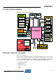
AVR32907 3 AT32UC3C-EK block diagram Figure 3-1.
4.1 Detailed hardware references (and associated errata) More detailed hardware information for this kit can be found in two places: • In the 32-bit AVR Studio®: contains the schematics, a logical block diagram, and the errata • The file AT32UC3C-EK_Hardware-References.zip, available on the Atmel web page dedicated to this kit: www.atmel.com/ The Atmel® AVR® AT32UC3C family of devices is specified in the UC3C Series datasheet.
AVR32907 4.4 Tools To be able to develop applications for 32-bit AVR devices, build binaries for 32-bit AVR targets, and program a 32-bit AVR device, Atmel and its partners provide several tools supported on multiple host targets. 4.4.1 IDE and compilers: design software • 32-bit AVR Studio: 32-bit AVR Studio is a free integrated development environment (IDE) for AVR32 that enables you to write, build, deploy, and debug your C/C++ and assembler code.
Atmel Corporation 2325 Orchard Parkway San Jose, CA 95131 USA Tel: (+1)(408) 441-0311 Fax: (+1)(408) 487-2600 www.atmel.com Atmel Asia Limited Unit 01-5 & 16, 19F BEA Tower, Milennium City 5 418 Kwun Tong Road Kwun Tong, Kowloon HONG KONG Tel: (+852) 2245-6100 Fax: (+852) 2722-1369 Atmel Munich GmbH Business Campus Parkring 4 D-85748 Garching b. Munich GERMANY Tel: (+49) 89-31970-0 Fax: (+49) 89-3194621 Atmel Japan 9F, Tonetsu Shinkawa Bldg.