
User manual

AVR32919
32151A-AVR-09/10
4.1.2 UC3C-Specific Information
4.1.2.1 AT32UC3C0512C Power Supply Mode
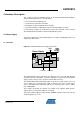
Among the two power supply configurations supported by the Atmel
AT32UC3C0512C, this board implements the 3.3V Single Supply Mode
configuration. Refer to the Figure “3.3V Single Supply mode” of the Power
Considerations section in the AVR UC3 C0 Series datasheet
for schematic diagram
of this mode.
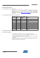
4.1.2.2 AT32UC3C0512C pinout for the Power Supply Block
Table 4-1. UC3C pinout for the Power Supply block
QFP144 pin GPIO
GPIO alternate
function
Feature
53 N.A. N.A. VDDIN5
54 N.A. N.A. VDDIN33
52 N.A. N.A. GNDPLL
55 N.A. N.A. VDDCORE
56 N.A N.A GNDCORE
37 N.A. N.A. GNDANA
34,35 N.A. N.A. ADCREFP/N
38 N.A. N.A. VDDANA
5,76,104,119 N.A. N.A GNDVDDIO
5,75,103,118 N.A. N.A. VDDIO
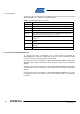
4.1.3 Configurations and Test Points
4.1.3.1 Hardware Configurations
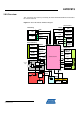
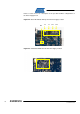
The default hardware configuration of the Power Supply block implies that:
• The power supply source is one of the 2x USB plug –“USB USER” and “USB
VCP”- or the jack header (ref. Figure 4-1 and Figure 3-1),
• The 2-pins header (J2) can also be used as a power supply source (not available
by default).
Mount the 0 Ohm R73 resistor (solder strap) and remove the 0 Ohm R71 resistor, to
enable the 2-pins header external entry (J2).