
User manual

AVR32919
32151A-AVR-09/10
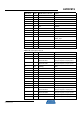
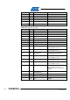
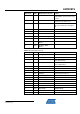
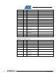
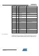
QFP144 pin GPIO GPIO alternate function Feature
115 PD8 EBI A4 SDRAM Address Bus
116 PD9 EBI A5 SDRAM Address Bus
117 PD10 EBI A6 SDRAM Address Bus
120 PD11 EBI A7 SDRAM Address Bus
121 PD12 EBI A8 SDRAM Address Bus
122 PD13 EBI SDCK SDRAM Clock
123 PD14 EBI A10 SDRAM Address Bus
124 PD15
EBI A11 / Software-
dependant
SDRAM Address Bus / J20.6
125 PD16
EBI-A12/ Software-
dependant
TFT Reset Signal / J20.7
126 PD17 EBI-A13 SDRAM Address Bus
127 PD18 EBI-A14 SDRAM Address Bus
128 PD19 EBI-A15 TFT TE Signal
129 PD20 EBI-A16 SDRAM Address Bus
130 PD21 EBI-A17 SDRAM Address Bus
131 PD22 GPIO[118] or TC0-A2 LED3
132 PD23 GPIO[119] LED1
97 PD24 EBI DQM1 SDRAM DQM1
134 PD25 EBI-NWE0 TFT Write Signal
135 PD26 EBI-NRD TFT Read Signal
136 PD27 EBI CS SDRAM CS
137 PD28 GPIO[124] or TC0-B0 TFT Backlight Signal.
138 PD29 N.A EVTO_N
139 PD30 GPIO[28] SD Write Protect
4.9.2.1 Configuration
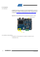
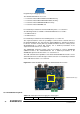
A USB DFU Bootloader is pre-loaded on the Atmel AT32UC3C0512C. To enter this
bootloader mode, the PB0 push-button must be pressed upon reset then released. It
is then possible to program the AT32UC3C0512C through the USB DFU Bootloader.