
User manual

4
AVR32919
32151A-AVR-09/10
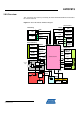
3.1 Features
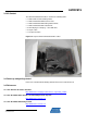
This section lists the main components and interfaces of the Atmel AT32UC3C-EK kit:
• Main MCU: 32-bit Atmel AVR UC3 AT32UC3C0512C (TQFP144)
o 512 Kbytes internal Flash, 256 Kbytes internal RAM
o Up to 66 MHz operations
o Controller Area Network Interfaces
o Peripheral Event System
o FlashVault™ allows pre-programmed Secure library support for end-
user applications
o DSP Floating Point Instructions.
• Powered through USB connector or through external power supply (header J1 or
J2).
• 16 MHz oscillator for the main clock, 1x RTC 32 kHz crystal and 1x free footprint
for additional oscillator.
• JTAG and NEXUS Connectors for programming and debugging on the Atmel
AT32UC3C0512C MCU.
• 4x LEDs.
• 2x pushbuttons.
• 1x reset pushbutton.
• 1x QTouch
®
(Atmel AT42QT1060) with 6x buttons connected through the TWI.
• 1x QVGA LCD display with resistive touch screen.
• 1x jack connector to output audio samples.
• 1x microphone input to record audio signal.
• 2x CAN Interfaces and 2x LIN Interfaces.
• 1x serial DataFlash 64 Mbits.
• 1x serial EEPROM 128 bits.
• 1x SD/MMC slot connector.
• 1x SDRAM 256 Mbits.
• Wireless Header (WLESS) for the wireless expansion header or for any SPI-based
or TWI-based or USART-based external communication.
• Atmel AVRMC300 expansion headers to be able to manage motor control
applications.
• J27: USB (2.0 mini A-B receptacle) connected to the 32-bit Atmel AVR UC3
AT32UC3B1256
o AT32UC3C0512C and Atmel AT32UC3B1256 are connected through
2 pins.
o The pre-loaded firmware on the AT32UC3B1256 acts as a UART-
USB CDC Virtual Com Port gateway.
o the J28 jumper can be used to set the AT32UC3B1256 in bootloader
mode at power-up.
o JTAG connector for programming & debugging the AT32UC3B1256.
• J21: USB (2.0 mini A-B receptacle) connected to the 32-bit AVR UC3
AT32UC3C0512C to demonstrate USB feature of the product.