
User manual

28
AVR32919
32151A-AVR-09/10
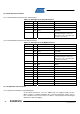
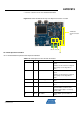
Table 4-23. UC3C pinout for the hall sensors (J43)
QFP144 pin GPIO GPIO alternate function Feature
66 PB27 QDEC – QEPA Quadrature Decoder Line A
67 PB28 QDEC – QEPB Quadrature Decoder Line B
68 PB29 QDEC – QEPI Quadrature Decoder Line I
- - - GND on J43.5
- - - VCC3 on J43.1
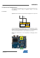
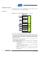
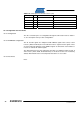
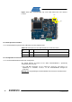
4.6.3 Configuration and Test Points
4.6.3.1 Configuration
The J25.1 and J25.2 pins are configurable through the J44 header. Refer to Table 4-
17, for a description of the possible configurations.
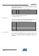
4.6.3.2 AVRMC300 Configuration
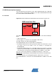
The XL and XH signals are multiplexed with NEXUS signals. Due to that, 0 ohm
resistors (R160 and R162) are inserted between these signals and I/O signals. There
are not mounted by default. It means NEXUS signals are functional. Just mount these
resistors to activate XL and XH signals.
The differential measures and comparator detections are multiplexed. Due to that, 0
ohm resistors (R157, R158, R159 and R161) are inserted. As there are mounted by
default, differential measures and comparator detections are accessible.
4.6.3.3 Test Points
None.