
User manual

AVR32919
32151A-AVR-09/10
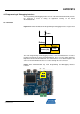
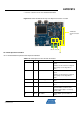
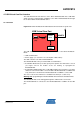
Table 4-20. UC3C pinout for the power drives control signal (J33)
QFP144 pin GPIO GPIO alternate function Feature
12 PB9 PWM-PWMH[0]
Provides access to the PWM UH signal
available on J33.1
11 PB8 PWM-PWML[0]
Provides access to the PWM UL signal
available on J33.2
14 PB11 PWM-PWMH[1]
Provides access to the PWM VH signal
available on J33.3
13 PB10 PWM-PWML[1]
Provides access to the PWM VL signal
available on J33.4
16 PB13 PWM-PWMH[2]
Provides access to the PWM WH
signal available on J33.5
15 PB12 PWM-PWML[2]
Provides access to the PWM WL signal
available on J33.6
18 PB15 PWM-PWMH[3]
Provides access to the PWM XH signal
available on J33.5. See configuration
section to activate this feature
17 PB14 PWM-PWML[3]
Provides access to the PWM XL signal
available on J33.6. See configuration
section to activate this feature
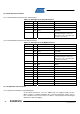
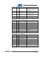
Table 4-21. UC3C pinout for the current and back EMF measurement (J38)
QFP144 pin GPIO GPIO alternate function Feature
23 PA6
ADCIFA-ADCIN2 or
ACIFA-AC1AP1
ADC Input 0 positive channel or Analog
Comparator 0 Input positive. See
section AVRMC300 Configuration to
select one of the two features
23 PA7
ADCIFA-ADCIN3 or
ACIFA-AC1AN1
ADC Input 1 positive channel or Analog
Comparator 0 Input negative. See
section AVRMC300 Configuration to
select one of the two features
39 PA20
ADCIFA-ADCIN9 or
ACIFA-AC0AP0
ADC Input 0 negative channel or
Analog Comparator 1 Input positive.
See section AVRMC300 Configuration
to select one of the two features
41 PA22 ACIFA-AC0AN0 Analog Comparator 1 Input negative
42 PA23 ACIFA-AC0BP0 Analog Comparator 2 Input positive
40 PA21
ADCIFA-ADCIN10 or
ACIFA-AC0BN0
ADC Input 1 negative channel or
Analog Comparator 2 Input negative.
See section AVRMC300 Configuration
to select one of the two features
29 PA12 DACIFB-DAC1A DAC Output
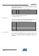
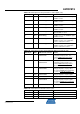
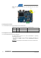
Table 4-22. UC3C pinout for the hall sensors (J41)
QFP144 pin GPIO GPIO alternate function Feature
66 PB27 GPIO[59] -
67 PB28 GPIO[60] -
68 PB29 GPIO[61] -