
User manual

AVR32919
32151A-AVR-09/10
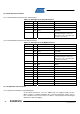
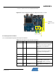
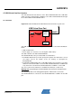
Table 4-15 highlights the components of the Atmel AT32UC3C-EK that might interfere
with the multiplexed NEXUS pins. These components must not be used while
debugging with the NEXUS interface.
Table 4-15. Conflicts Conditions over the NEXUS Debugging Pins
QFP144 pin GPIO Conflict conditions
18 PB15 Nexus pin in conflict with Wireless (WLESS) CTS Signal
17 PB14 Nexus pin in conflict with Wireless (WLESS) RTS Signal
64 PB25 Nexus pin in conflict with Wireless (WLESS) CS Signal
To summarize, debugging on NEXUS will not work if:
• The WLESS connector is used.
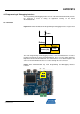
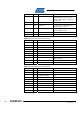
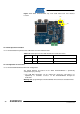
4.5.3.2 Test Points
A few test points covering the Programming and Debugging Interface block have
been placed on the AT32UC3C-EK for the verification of important signals.
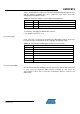
Table 4-16. Programming and Debugging Interface block Test Points
Designation Feature
TP57 JTAG.TCK
TP58 JTAG.TDO
TP59 JTAG.TMS
TP60 JTAG.TDI
TP61 GND
TP62 VCC3
TP63 RESET_N
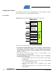
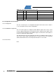
4.5.3.3 Using the aWire
The Atmel AVR ONE! and JTAGICE mkII tools can interface with the Atmel AVR UC3
C series using the single-wire aWire interface available on J24. Check the
documentation of these tools to know the recommended pinout to connect to an
aWire target.