
User manual

AVR32919
32151A-AVR-09/10
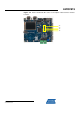
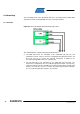
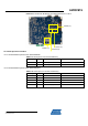
Figure 4-9. AT32UC3C-EK Top View Networking Location
4.3.2 UC3C-Specific Information
4.3.2.1 AT32UC3C0512C pinout for the User Interface block
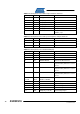
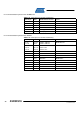
Table 4-7. UC3C pinout for the CAN interface
QFP144 pin GPIO GPIO alternate function Feature
36 PB04 RX CAN0 RX CAN
37 PB05 TX CAN0 TX CAN
84 PC11 RX CAN1 RX CAN
85 PC12 TX CAN1 TX CAN
Table 4-8. UC3C pinout for the LIN interfaces
QFP144 pin GPIO GPIO alternate function Feature
19 PB16 RX LIN0 RX LIN
20 PB17 TX LIN0 TX LIN
88 PC15 RX LIN1 RX LIN
89 PC16 TX LIN1 TX LIN
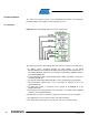
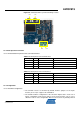
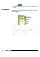
4.3.3 Configuration
4.3.3.1 Hardware Configuration
• The terminal resistors are mounted by default. Remove jumpers on the 2-pins
headers (J9 or J14) to suppress this termination.
• The default hardware configuration of the LIN block implies that 2 nodes are in
master configuration. Only remove jumpers on the 2-pins headers (J12 or J17) to
switch the node in slave configuration. Moreover, the board is by default powered
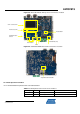
J10
J15
J13 J18