
User manual

14
AVR32919
32151A-AVR-09/10
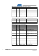
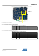
Table 4-4. UC3C pinout for the LEDs and push-buttons interfaces
QFP144 pin GPIO GPIO alternate function Feature
25 PA8 GPIO[8] LED0
132 PD23 GPIO[119] LED1
86 PC13 GPIO[77] or PWMH[2] LED2
131 PD22 GPIO[118] or TC0-A2 LED3
31 PA14 GPIO[14] PB0 push-button
48 PA29 GPIO[29] or EXTINT[0] PB1 push-button
N.A. N.A.
RST push-button, connected to the
RESET_N pin
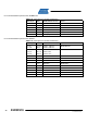
Table 4-5. UC3C pinout for the audio jack, microphone and potentiometer
QFP144 pin GPIO GPIO alternate function Feature
44 PA25 ADCIFA-ADCIN14 Microphone Input
32 PA15 DACIFB-DAC1B Jack Audio
26 PA9 ADCIFA-ADCIN5 Potentiometer
Table 4-6. UC3C pinout for the QVGA LCD Display
QFP144 pin GPIO GPIO alternate function Feature
22 PA5 ADCIFA-ADCIN1 TFT YU Line Measurement
30 PA13 ADCIFA-ADCIN15 TFT YD Line Measurement
43 PA24 ADCIFA-ADCIN13 TFT XR Line Measurement
21 PA4 ADCIFA-ADCIN0 TFT XL Line Measurement
58 PB19 SPI1-MOSI
TFT Interface through the SPI is not
implemented by default. See section
4.1.3.1
59 PB20 SPI1-MISO
TFT Interface through the SPI is not
implemented by default. See section
4.1.3.1
60 PB21 SPI1-SCKI
TFT Interface through the SPI is not
implemented by default. See section
4.1.3.1
92-106
107-109
PC19-31
PD0-2
EBI-D0 – EBI-D12
EBI-D13 – EBI-D15
TFT Data Bus
128 PD19 EBI-A15 TFT TE Signal
134 PD25 EBI-NWE0 TFT Write Signal
135 PD26 EBI-NRD TFT Read Signal
125 PD16 EBI-16 TFT Reset Signal
137 PD28 GPIO[124] or TC0-B0 TFT Backlight Signal