
User manual

10
AVR32919
32151A-AVR-09/10
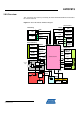
4.1.3.2 Test Points
A few test points covering the Power Supply block have been placed on the Atmel
AT32UC3C-EK for the verification of important signals.
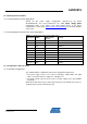
Table 4-2. Power Supply block Test Points
Designation Feature
TP12-14 Input voltage level after D1 when the J1 external Power Supply is used
TP20-21 Input voltage level after D2 when the J2 external Power Supply is used
TP22-23 Input voltage for 3.3V regulator. 5V nominal
TP24-25 Input voltage for all board components. 3.3V nominal
TP28-31
Input voltage for all board components except Atmel AT32UC3C0512C
and Atmel AT42QT1080. Should be 3.3V nominal
TP27-30
Input voltage for the AT32UC3C0512C VDDIO pin. Should be 3.3V
nominal
TP26-29
Input voltage for the AT32UC3C0512C VDDIN pin. Should be 3.3V
nominal
TP32-33
Input voltage for the AT32UC3C0512C VDDANA pin. Should be 3.3V
nominal
TP13 GND
.
4.1.4 Power Consumption Measurement
To measure the power consumption of the overall board not including the
AT32UC3C0512C, remove the 0 Ohm R24, 25, 26, 27 resistors and insert the amp
meter in the 2-pins header J6 (not mounted by default).
To measure the power consumption on the AT32UC3C0512C VDDIO, remove the 0
Ohm R26 resistor and insert the amp meter in the 2-pins header J5 (not mounted by
default).
To measure the power consumption on the AT32UC3C0512C VDDIN, remove the 0
Ohm R25 resistor and insert the amp meter in the 2-pins header J4 (not mounted by
default).
To measure the power consumption on the AT32UC3C0512C VDDANA, remove the
0 Ohm R24 resistor and insert the amp meter in the 2-pins header J3 (not mounted
by default).