
User manual


6
AVR32930
32163A-AVR-03/11
4 Connecting the board
Connect a USB cable (Standard-A to Mini-B or Mini-AB) between the board and a PC
or a USB power supply to power it up. That is all that is needed. When power is
applied, the Power/Status LED will light up green.
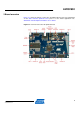
WARNING Do not power the board without having the jumper or an ammeter
mounted on the power measurement header. Otherwise, the device
may be damaged. The power measurement header is located next to
the USB connector, as shown in Figure 3-1.
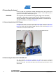
4.1 Connecting the Atmel AVR Dragon
A 10-pin header cable is needed to connect the AVR Dragon tool to the Atmel UC3-
A3 Xplained board. Connect the cable between the JTAG connector on the AVR
Dragon kit and the UC3-A3 Xplained JTAG connector. Take a look at Figure 4-1 to
see how the connection should be made.
Figure 4-1. Connecting the AVR Dragon tool to the UC3-A3 Xplained board.
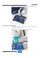
4.2 Connecting the Atmel AVR JTAGICE mkII
The grey connector on the AVR JTAGICE mkII probe has to be used when
connecting to the UC3-A3 Xplained board. See Figure 4-2 for reference on how to
make the connection. The notch of the grey connector must be placed into the cut-out
of the board.