
User manual

Atmel AVR32918: UC3-A3 Xplained Hardware User’s Guide [APPLICATION NOTE]
32159C−AVR−07/2012
7
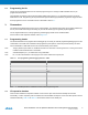
Table 3-5. UC3 I/O expansion header – J4.
Pin J4 UC3 pin Shared with onboard functionality
1 TWI1 SCL
(1)
PA14/PA15 USART1 RTS
2 TWI1 SDA
(1)
PA15/PA12 USART1 CTS
3 USART1 RXD PA05 -
4 USART1 TXD PA06 -
5 SPI0 CS3 PA07 -
6 SPI0 MOSI PA10 Serial flash/DataFlash
7 SPI0 MISO PA11 Serial flash/DataFlash
8 SPI0 SCK PA08 Serial flash/DataFlash
9 GND - -
10 VCC_P3V3 - -
Note: 1. See known issues Section 7.1.1.1 Swapped TWI SCL and TWI SDA on header J4.
4. Memories
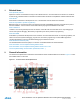
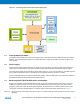
The Atmel UC3-A3 Xplained has an external SDRAM memory mounted on the board. There are also footprints
available for adding either an industrial standard or a proprietary Atmel DataFlash serial flash.
Note: The footprints share the same SPI lines including the chip select, and so it is not possible to mount a device on both
footprints at the same time.
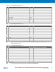
Table 4-1. Compatible devices for the footprints.
Atmel AT45DB Atmel AT25DF
AT45DB64D2-CNU AT25DF641A-SH
AT45DB321D-MWU AT25DF321A-SH
AT45DB161D-SS AT25DF161-SH
AT45DB081D-SS AT25DF081-SSH
AT45DB041D-SS AT25DF021-SSH
AT45DB021D-SS
AT45DB011D-SS
5. Miscellaneous I/O
5.1 Mechanical button
The board is equipped with one mechanical button. Because the button is used to enter bootloader mode it has a pull-
up mounted, this means it is not necessary to use the pull-up in the UC3 to detect the status of the button.
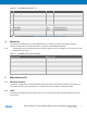
5.2 LEDs
The Atmel UC3-A3 Xplained has four yellow LEDs which are connected to the Atmel AT32UC3A3256 and all of them
are active low.