
User manual

Atmel AVR32918: UC3-A3 Xplained Hardware User’s Guide [APPLICATION NOTE]
32159C−AVR−07/2012
5
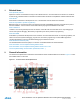
2.4 Programming the kit
The kit can be programmed either from an external programming tool or through a USB bootloader which is pre-
programmed on the device.
The bootloader is evoked by pushing the push button (SW0) during power-on. I.e. push button and then connect an
USB cable to the kit. Programming can be performed through the DFU target (bootloader programmer target) with FLIP.
How a programmer can be connected to the kit is described in Section 3.1.
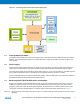
3. Connectors
The Atmel UC3-A3 Xplained kit has five 10-pin, 100mil headers. Two headers have a fixed communication interface (J1
and J4). One header has analog functionality (J2), and the last header (J3) has general purpose digital I/O.
The 90° angled header is the JTAG programming and debugging header for the AT32UC3A3256.
For the location of the respective headers, refer to Figure 2-1.
3.1 Programming header
The AT32UC3A3256 can be programmed and debugged by connecting an external programming/debugging tool to the
JTAG header. The header has a standard JTAG programmer pinout (refer to online help in Atmel Studio), and tools
such as JTAGICE3 or AVR ONE! can thus be connected directly to the header.
Note: The grey female 10-pin header on JTAGICE mkII has to be used when connecting to the kit. A scoring in the board
is made to fit the orientation tab on the header.
Note: A standoff adapter (no. 1) is needed when using AVR ONE!.
Note: Pin 1 on the JTAG header is at the top right corner and is marked with a square pad.
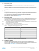
Table 3-1. UC3 programming and debugging interface - JTAG.
Pin JTAG
(1)
1 TCK
2 GND
3 TDO
4 VCC
5 TMS
6 nSRST
7 -
8 -
9 TDI
10 GND
Note: 1. Standard pinout for JTAGICE3 and other Atmel programming tools.
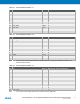
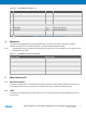
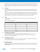
3.2 I/O expansion headers
There are four available I/O expansion headers on the kit. Some pins have shared functionality with onboard
functionality. If “clean” expansion ports are needed, there are available cut-straps on some of the ADC inputs to remove
onboard functionality. Table 3-2 to Table 3-5 show
what is shared on the header pins.