MCP3903 ADC Evaluation Board for 16-Bit MCUs User’s Guide © 2011 Microchip Technology Inc.
Note the following details of the code protection feature on Microchip devices: • Microchip products meet the specification contained in their particular Microchip Data Sheet. • Microchip believes that its family of products is one of the most secure families of its kind on the market today, when used in the intended manner and under normal conditions. • There are dishonest and possibly illegal methods used to breach the code protection feature.
MCP3903 ADC EVALUATION BOARD FOR 16-BIT MCUs USER’S GUIDE Table of Contents Preface ........................................................................................................................... 1 Introduction............................................................................................................ 1 Document Layout .................................................................................................. 1 Conventions Used in this Guide ...............................
MCP3903 ADC Evaluation Board for 16-Bit MCUs User’s Guide DS51994A-page 4 © 2011 Microchip Technology Inc.
MCP3903 ADC EVALUATION BOARD FOR 16-BIT MCUs USER’S GUIDE Preface NOTICE TO CUSTOMERS All documentation becomes dated, and this manual is no exception. Microchip tools and documentation are constantly evolving to meet customer needs, so some actual dialogs and/or tool descriptions may differ from those in this document. Please refer to our web site (www.microchip.com) to obtain the latest documentation available. Documents are identified with a “DS” number.
MCP3903 ADC Evaluation Board for 16-Bit MCUs User’s Guide CONVENTIONS USED IN THIS GUIDE This manual uses the following documentation conventions: DOCUMENTATION CONVENTIONS Description Arial font: Italic characters Initial caps Quotes Underlined, italic text with right angle bracket Bold characters N‘Rnnnn Text in angle brackets < > Courier New font: Plain Courier New Represents Referenced books Emphasized text A window A dialog A menu selection A field name in a window or dialog A menu path MPLAB® IDE
Preface RECOMMENDED READING This User's Guide describes how to use MCP3903 ADC Evaluation Board for 16-Bit MCUs. Other useful documents are listed below. The following Microchip document is available and recommended as a supplemental reference resource: • MCP3903 Data Sheet - “Six Channel Delta Sigma A/D Converter” (DS25048B) THE MICROCHIP WEB SITE Microchip provides online support via our web site at www.microchip.com.
MCP3903 ADC Evaluation Board for 16-Bit MCUs User’s Guide NOTES: DS51994A-page 4 © 2011 Microchip Technology Inc.
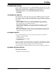
MCP3903 ADC EVALUATION BOARD FOR 16-BIT MCUs USER’S GUIDE Chapter 1. Hardware Description 1.1 OVERVIEW The MCP3903 ADC Evaluation Board for 16-Bit MCUs system lets users evaluate the performance of the MCP3903 six-channel ADC. It also provides a development platform for 16-bit PIC® MCU-based applications, using existing 100-pin PIM systems, compatible with the Explorer-16 and other high pincount PIC demo boards.
MCP3903 ADC Evaluation Board for 16-Bit MCUs User’s Guide FIGURE 1-1: DS51994A-page 6 MCP3903 ADC Evaluation Board for 16-Bit MCUs. © 2011 Microchip Technology Inc.
Hardware Description 1.2 PIM MODULE / MCP3903 CONNECTION AND PERIPHERAL USAGE OVERVIEW The MCP3903 ADC Evaluation Board for 16-Bit MCUs contains a 100-pin PIM socket, compatible with Microchip’s PIM modules. The system comes with a PIM module: the PIC24FJ128GA010. For a complete description of the firmware programmed with these two modules, see Chapter 1. “Hardware Description”.
MCP3903 ADC Evaluation Board for 16-Bit MCUs User’s Guide 1.2.1 Using the Crystal X2 The MCP3903 ADC Evaluation Board for 16-Bit MCUs is populated with a 3.58 MHz crystal, being used as a clock source, by placing jumpers in the following position on the MCP3903 Digital I/O header block: CLKOUT CLKIN CLKIN FIGURE 1-3: 1.2.2 XTAL XTAL PIM OC1 ADC Clock Selection Jumpers - External Crystal.
Hardware Description 1.3 ANALOG INPUT STRUCTURE Two differential input paths allow external signal sources to be easily connected to the MCP3903 input. Edge connectors JP1 and JP2 are 3-pin connectors that act both as crew-type and clip-on post connectors. Note: To use an edge connector as a post connector, pull up the blue plastic top to access the posts. JP1 and JP2 can be used to force either channel from a differential to a single-ended configuration.
MCP3903 ADC Evaluation Board for 16-Bit MCUs User’s Guide NOTES: DS51994A-page 10 © 2011 Microchip Technology Inc.
MCP3903 ADC EVALUATION BOARD FOR 16-BIT MCUs USER’S GUIDE Chapter 2. Code Example 2.1 DSPIC33 EXAMPLE DESCRIPTION If the user needs to evaluate the ADC on a system that uses dsPIC33 microcontrollers, then a PIM connector with a dsPIC33FJ256GA710A can be used on the evaluation board. Using this example, the user can modify all MCP3903 internal registers from the PC software “MCP390x Data VIEW”. The UART communication speed is at 115.2 kbps. 2.1.
MCP3903 ADC Evaluation Board for 16-Bit MCUs User’s Guide S ta r t Initialization In itia lis a tio n G e t s a m p le s in to b u ffe r [5 1 2 ] R e a d In te r n a l R e g is te rs W a it fo r P C G U I com m and C om m and re c e iv e d NO YES C h e c k v a lid ity C o m m a n d v a lid NO YES W r ite in te r n a l re g is te rs S e n d s a m p le s fr o m B u ffe r [5 1 2 ] S e n d in te r n a l re g is te r s Send FFT ( n o t c o m p u te d h e re ) U p d a te c h a n n e ls s e le c tio
Code Example FIGURE 2-2: MCP3903 Data View Software - Main Screen. Connectivity is done through the serial port. First, the user must identify the com port number from My computer > Manage > Device Manager. After this, in “VISA resource names”, users must find and select the correct com port number. Only after this, can the START button be pressed to begin the data acquisition. FIGURE 2-3: MCP3903 Data View Software - Registers and Settings Screen.
MCP3903 ADC Evaluation Board for 16-Bit MCUs User’s Guide The Waveform Graphs will show the signal in Time domain, while the Signal Spectrum graphs shows the signal in Frequency domain. From the Graphs menu, under the Signal Spectrum option, the user can find the Switch Y-axis scale option. From here, it is possible to change the Y axis of the Signal Spectrum in linear scale or in logarithmic scale.
MCP3903 ADC EVALUATION BOARD FOR 16-BIT MCUs USER’S GUIDE Appendix A. Schematics and Layouts A.1 INTRODUCTION This appendix contains the following schematics of the MCP3903 ADC Evaluation Board for 16-Bit MCUs.
DS51994A-page 16 4 3 P1A CH1+ P5B GND A P5C CH5- P5A P4A CH4- CH5+ P4B GND P3A CH3+ P4C P3B GND CH4+ P3C P2A CH3- CH2- P2B P1B GND GND P1C CH1- P2C P0A CH0- CH2+ P0B GND P0C 1 2 3 1 2 3 1 2 3 1 2 3 1 2 3 1 2 3 GNDA GNDA GNDA GNDA GNDA GNDA NET00088 GNDA GNDA GNDA GNDA GNDA DNP R2 GNDA GNDA DNP R1 DNP R4 GNDA GNDA DNP R3 DNP R92 DNP R89 DNP R90 GNDA DNP R91 DNP R104 DNP R101 C G GNDA DNP R102 NET00093 G GNDA D
© 2011 Microchip Technology Inc. 4 3 +3.3V +5V C12 100NF NET00052 +3.3V GNDA GNDA 1.3K R16 10K R15 A VEE R17 NONE R18 NONE GNDA +3.
4 3 2 A GNDA GNDA GNDA GNDA B3S-1002P SW4 B3S-1002P SW3 B3S-1002P SW2 B3S-1002P SW1 +3.3V +3.3V C11 100NF 4.7K GNDA R20 R24 R14 +3.3V R13 GNDA C13 100NF 4.7K R19 GNDA C21 100NF 4.7K R23 GNDA C29 100NF R31 1K 1K 1K 1K B 6 5 4 3 2 1 HDR6X1 P6 PIC24 ICD RD13 RD6 RD7 PIC24_MCLR GNDA +3.
4 3 A GNDA X1 470 R44 B C39 0.1uF 3 RESONATOR-CSTCE 12MHz GREEN 2 B 2 4 © 2011 Microchip Technology Inc. 470 R41 GNDA RED R47 D1 USB_+5V U5 VSS D+ DVUSB GP0/SSPND GP1/USBCFG GP2 CTS RX RTS MCP2200_SSOP20 VDD OSC1 OSC2 RST GP7/TxLED GP6/RxLED GP5 GP4 GP3 TX GNDA C 0.1uF C41 MCP2200 C J5 U5-RX RF2/U1RX U6RX RF3/U1TX HDR1X3 GNDA D+ D- USB_+5V 5 4 3 2 1 USB D J2E J2D J2C J2B J2A DATAVIEW PORT D E E Filename: MCP2200 _ USB.
4 3 A USB_SCK USB_SS USB_SDI USB_SDO RG15 RB0/AN0 RB1/AN1 RB2/SS1/AN2 RB3/AN3 RB4/AN4 RB5/AN5 RE9/INT2 RE8/INT1 RA0/TMS PIC24_MCLR RC4 RC3 RC2 RE7/PMPD7 RE6/PMPD6 RE5/PMPD5 +3.3V GNDA +3.
4 3 2 A J1 RAPC722 +9V IN 1 3 2 POWER K D3 GNDAMBR0520LT1 A GNDA C4 10UF +9V 3 IN U1 2 EXT +5V POWER GNDA OUT LM1117-5.0 GND 1 © 2011 Microchip Technology Inc. GNDA P11A B P11B C3 100NF B GNDA POWER.SCHDOC EXT_+5V Filename: 1 2 USB_+5V POWER JP3 1 2 HDR3X2 3 5 4 6 EXT +5V +9V IN USB 4.7UF C6 GNDA 3 IN C2 4.7UF C GNDA U3 LM1117-3.3 OUT GNDA C 1 L1 10UH 2 GNDA C1 10UF +5V +3.3V 100NF C5 GNDA POWER BLUE GM1B55250AC D5 1 Rev +3.
MCP3903 ADC Evaluation Board for 16-Bit MCUs User’s Guide A.8 BOARD - TOP TRACE AND TOP SILK A.9 BOARD - BOTTOM TRACE AND BOTTOM SILK DS51994A-page 22 © 2011 Microchip Technology Inc.
Schematics and Layouts A.10 BOARD - LAYER #2 VDD A.11 BOARD - LAYER #3 GND © 2011 Microchip Technology Inc.
MCP3903 ADC Evaluation Board for 16-Bit MCUs User’s Guide A.12 BOARD - TOP SILK AND PADS A.13 BOARD - BOTTOM SILK AND PADS DS51994A-page 24 © 2011 Microchip Technology Inc.
MCP3903 ADC EVALUATION BOARD FOR 16-BIT MCUs USER’S GUIDE Appendix B. Bill of Materials (BOM) TABLE B-1: Qty BILL OF MATERIALS (BOM) Reference Description Manufacturer Part Number 2 C1,C4 CAP CER 10UF 16V Y5V 0805 TDK Corp. C2012Y5V1C106Z 25 C11<>C22 C24<>C30 C33,C34,C35 C36,C39,C41 CAP CER .10UF 25V X7R 10% 0603 TDK Corp. C1608X7R1E104K 2 C2,C6 CAP CER 4.7UF 25V Y5V 0805 TDK Corp. C2012Y5V1E475Z T491A476M006AT 1 C23 CAPACITOR TANT 47UF 6.
Bill of Materials (BOM) TABLE B-1: Qty BILL OF MATERIALS (BOM) (CONTINUED) Reference Description Manufacturer 1 L1 Shielded 10uH Power Inductor 0805 1 LCD1 "DO NOT INSTALL" 1 LCD2 16X2 FTN Reflective No. BLWT COG 3V Tianma TM162JCAWG1 4 MOD1 25 X 1 Header 1.27mm on center Samtec MTMS-125-01-G-S-230 6 P0,P1,P2,P3 P4,P5 CONN TERM BLK PLUG 6A 3.
Bill of Materials (BOM) TABLE B-1: Qty BILL OF MATERIALS (BOM) (CONTINUED) Reference Description Manufacturer Part Number 12 R5,R7,R11 R12,R83,R85 R86,R88,R95 R97,R98 R100 RES 1.0K OHM .1% 1/4W 0805 SMD Susumu Co., LTD. RGH2012-2E-P-102-B 2 R59,R60 RES 10.0 OHM 1/8W 1% 0805 SMD Rohm Semi. MCR10EZHF10R0 4 SW1,SW2 SW3,SW4 SWITCH TACT 6MM 230GF H=4.3MM Omron Electronic Components ECB Division B3S-1002P 1 TP1 Wire Test Point 0.3" Length Components Corp.
Worldwide Sales and Service AMERICAS ASIA/PACIFIC ASIA/PACIFIC EUROPE Corporate Office 2355 West Chandler Blvd. Chandler, AZ 85224-6199 Tel: 480-792-7200 Fax: 480-792-7277 Technical Support: http://www.microchip.com/ support Web Address: www.microchip.