
User manual


MPLAB
®
REAL ICE
™
In-Circuit Emulator User’s Guide
DS51616B-page 122 © 2008 Microchip Technology Inc.
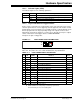
12.8 LOOP-BACK TEST BOARD
This board can be used to verify that the emulator is functioning properly. To use this
board:
1. Disconnect the emulator from the target and the PC.
2. Insert the standard driver board if it is not already installed.
3. Connect the loop-back test board to the emulator using the modular cable.
4. Plug the loop-back test board into the emulator’s logic probe socket, modular
cable connector side up
5. Connect the emulator to the PC.
6. Select the MPLAB REAL ICE in-circuit emulator as either a debugger or
programmer in MPLAB IDE.
7. Select Debugger>Settings
or Programmer>Settings, Status tab, and click Run
Loopback Test.
MPLAB IDE will detect and run the complete loop-back test and give you a status
(PASS/FAIL). The loop-back test board detection works by applying a short pulse on
EXT0 and detecting it on EXT7 on the logic probe connector (Section 12.5.4 “Logic
Probe/External Trigger Interface”). Once the board is detected, the emulator applies
stimulus to the clock/data and V
PP lines and reads the sequence back from the logic
probe connector interface, thus confirming proper signals levels and connectivity down
to the connector interfaces.
12.9 TARGET BOARD CONSIDERATIONS
The target board should be powered according to the requirements of the selected
device (1.6V-5.5V) and the application.
The emulator does sense target power. There is a 10 KΩ load on V
DD_TGT.
Depending on the type of emulator-to-target communications used, there will be some
considerations for target board circuitry:
• Section 2.4.3 “Target Connection Circuitry”
• Section 2.4.4 “Circuits That Will Prevent the Emulator From Functioning”
Emulator
Pod
Standard Driver Board
Loop-Back Test Board
Modular Cable
Logic Probe Connector
Driver Board Slot
Note: The emulator cannot power the target.