
User manual


Hardware Specification
© 2008 Microchip Technology Inc. DS51616B-page 115
12.5.3 Indicator Lights (LEDs)
The indicator lights have the following significance.
12.5.4 Logic Probe/External Trigger Interface
Probes can be connected to the 14-pin header on the side of the unit for processing
external signals that are used for triggering external equipment. This header contains
8 input/output connections that are user selectable as inputs or outputs with logic levels
that are proportional to the target operating voltage. The outputs can be used for
triggering an external logic analyzer or oscilloscope to allow the developer to capture
events of interest based on trigger criteria set within MPLAB IDE.
The inputs are part of a trigger bus.
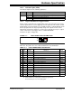
FIGURE 12-1: LOGIC PROBE PINOUT ON EMULATOR
Logic probes may be attached to this connector to give the functionality described in
Table 12-1. The probes are color coded and labeled for easy identification.
LED Color Description
Active Blue Lit when power is first applied or when target is connected.
Status Green Lit when the emulator is operating normally – standby.
Red Lit when an operation has failed.
Orange Lit when the emulator is busy.
TABLE 12-1: LOGIC PROBE PINOUT DESCRIPTION
Pin I/O Name Function Color
1O
VDD
(1)
VDD reference Red
2 O NC No connection Gray
3 O NC No connection Gray
4 I TCLK External synchronous clock Gray
5 I/O
EXT7
(2)
External input/output bit 7 White
6 I/O EXT6 External input/output bit 6 White
7 I/O EXT5 External input/output bit 5 White
8 I/O EXT4 External input/output bit 4 White
9 I/O EXT3 External input/output bit 3 White
10 I/O EXT2 External input/output bit 2 White
11 I/O EXT1 External input/output bit 1 White
12 I/O
EXT0
(2)
External input/output bit 0 White
13 Gnd GND System Ground Black
14 Gnd GND System Ground Black
Note 1: Do not connect V
DD to the target.
2: EXT0 and EXT7 are temporarily used during loop-back test.
Ensure that they are not connected together.
1*
2
13
14