
Data Sheet

24AA256/24LC256/24FC256
DS20001203X-page 12 1998-2021 Microchip Technology Inc.
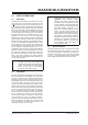
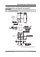
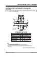
FIGURE 6-1: BYTE WRITE
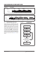
FIGURE 6-2: PAGE WRITE
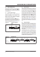
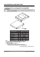
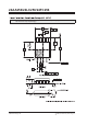
7.0 ACKNOWLEDGE POLLING
Since the device will not acknowledge during a write
cycle, this can be used to determine when the cycle is
complete (This feature can be used to maximize bus
throughput). Once the Stop condition for a write
command has been issued from the host, the device
initiates the internally timed write cycle. ACK polling
can be initiated immediately. This involves the host
sending a Start condition, followed by the control byte
for a write command (R/W
= 0). If the device is still
busy with the write cycle, then no ACK will be returned.
If no ACK is returned, the Start bit and control byte must
be resent. If the cycle is complete, then the device will
return the ACK and the host can then proceed with the
next read or write command. See Figure 7-1 for flow
diagram.
FIGURE 7-1: ACKNOWLEDGE
POLLING FLOW
x
Bus Activity
Host
SDA Line
Bus Activity
S
T
A
R
T
Control
Byte
Address
High Byte
Address
Low Byte
Data
S
T
O
P
A
C
K
A
C
K
A
C
K
A
C
K
x = dont care bit
S 1010 0
A
2
A
1
A
0
P
x
Bus Activity
Host
SDA Line
Bus Activity
S
T
A
R
T
Control
Byte
Address
High Byte
Address
Low Byte
Data Byte 0
S
T
O
P
A
C
K
A
C
K
A
C
K
A
C
K
Data Byte 63
A
C
K
x = dont care bit
S 1010 0
A
2
A
1
A
0
P
Send
Write Command
Send Stop
Condition to
Initiate Write Cycle
Send Start
Send Control Byte
with R/W = 0
Did Device
Acknowledge
(ACK = 0)?
Next
Operation
NO
YES