
User manual

USER MANUAL
m crob t
RRC-1258 MKII
mickes-reviderade- Ba1258B_RemoteRig_MkIIs-PA5.docx
Microbit 2.0 AB 2010. All rights reserved
User manual
Rev. PA8 – 23 Jan 2011
67 of 146
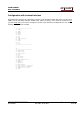
Codec inp preamp
Yes
Codec inp HPF Hz
163
163
COM0 baudrate
9600
9600
COM0 data bits
8
8
COM0 stop bits
1
1
COM0 parity
0 - Off
0 - Off
(*) Available only in RRC-1258MkIIs, remember that the bandwidth demand is doubled.
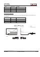
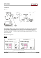
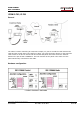
Connections
Drawings of the connection cables can be found under appendix B.
Control-RRC:
Connect a standard RS-232 cable between the PC and the RRC COM2.
The microphone can be connected direct to the RRC AUX/MIC connector if you have a
microphone with RJ-45 connector, like the HM-103. If you have a microphone with a
circular connector like HM-36 you can buy an adapter cable, OPC-589, from ICOM or make
one by yourself.
The speaker is connected direct to the RRC SP-jack with a 3.5 mm stereo plug.
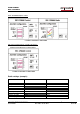
Radio-RRC:
From the RRC TTL connector to the radios CI-V jack you need to make a simple cable. The
cable should have a 4/6 modular connector in one end and a 3.5 mm stereo plug in the
other end. The 3.5 mm plug is connected to the radio CI-V jack.
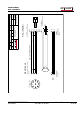
Between the RRC AUX/MIC connector and the radios microphone jack you can connect a
standard patch cable if the radio have a RJ-45 jack. If the radio have a circular
microphone jack you need to make an adapter cable by yourself or buy one from e.g. a
Tigertronics distributor (for Signallink), its article number is SLCAB8R. If you use
Tigertronic cable you need to put the straps different. If you make the cable by yourself,
just cut a standard FTP (screened) patch cable and solder an 8-pin circular connector on
it. Make the cable as short as possible to prevent it from picking up HF.
The speaker signal from the radios external speaker jack to the RRC SP jack is connected
via a standard "off- the-shelf” cable with 3.5 mm stereo plugs in both ends.