
User manual

USER MANUAL
m crob t
RRC-1258 MKII
mickes-reviderade- Ba1258B_RemoteRig_MkIIs-PA5.docx
Microbit 2.0 AB 2010. All rights reserved
User manual
Rev. PA8 – 23 Jan 2011
17 of 146
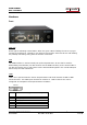
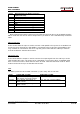
Pin no
PWR
+
+ 10-18 VDC (centre)
-
GND
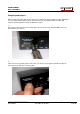
RESET
A short press on the reset switch will reboot the unit. By pressing and keep the button
pressed for 20 sec the unit reset to factory default settings with the following network
settings:
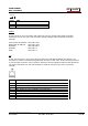
Control-RRC IP-address: 192.168.0.227
Radio-RRC IP-address: 192.168.0.228
Netmask: 255.255.255.0
Gateway: 192.168.0.1
DNS: 192.168.0.1
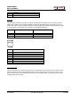
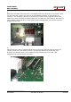
I/O
In the I/O connector is 3(2) inputs and 3 outputs, 8V and GND available (see below). The
connector is used for transferring signals from one RRC to the other. If the CW-keyer function
is not used the connector can be used for whatever controls signals needed in both directions.
The output transistor can sink max 200mA so install an external relay if it's not strong
enough.
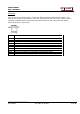
Pin no
I/O (RJ45)
1
IN1, active low (CW-Keyer right-paddle)
2
IN2, active low (CW-Keyer left-paddle)
3
OUT1, open collector
4
IN0, active low (only available at Control-RRC)
5
OUT0 open collector
6
OUT2 open collector
7
8V OUT (max 100mA)
8
GND
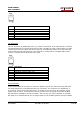
12V DC