
User manual


USER MANUAL
m crob t
RRC-1258 MKII
mickes-reviderade- Ba1258B_RemoteRig_MkIIs-PA5.docx
Microbit 2.0 AB 2010. All rights reserved
User manual
Rev. PA8 – 23 Jan 2011
111 of 146
4 RDO - serial data 57600 bps from radio to panel
5 TDO - serial data 57600 bps from panel to radio
6 AF - audio to speaker.
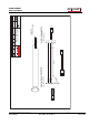
The easiest way to make these two cables from Control panel to Control-RRC TTL connector
and from Radio-RRC TTL connector to radio is to cut the cable supplied by Kenwood into two
pieces. You only have to crimp two new 6/6 modular connectors on the cables. Don't make
the one between Radio-RRC and radio to long.
The long Microphone extension cable supplied by Kenwood can also be used between Radio-
RRC AUX/MIC connector to the radio Microphone jack. Probably you need to cut it later to
prevent it from picking up HF from your antennas.
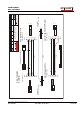
If the TS-480 is provided with a microphone with RJ-45 connector you can connect it directly
to the AUX/MIC connector on the Control-RRC. If it's provided with a circular 8 pin connector
you can used the adapter cable MJ-88 supplied by Kenwood with your TS-480 as a adapter
between the Microphone and the AUX/MIC connector.
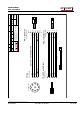
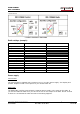
Connection type 1
Modular 8-pol connector:
3 MIC- mic Signal
4 MICE - mic ground
5 PTT
6 GND PTT
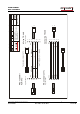
Connection type 2
Modular 8-pol connector:
3 MIC- mic Signal
4 GND PTT
5 PTT
6 MICE - mic ground
If you use the wrong configuration everything will work but the system will be very sensitive
for HF (RFI).
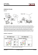
Power supply
Control-RRC:
The Control-RRC is supplied with a common 13,8 V (10-18V) power supply. The display and
speaker amplifier needs a lot of power so you need at least 1A.
Radio-RRC:
The Radio-RRC could be powered with a separate Power supply or the same as the radio. If
you use the Radio PS make sure you have a 1A fuse on the output to the RRC. Do not connect
it direct to a 20-40A PS the cable will melt if something happens.