
User manual

USER MANUAL
m crob t
RRC-1258 MKII
mickes-reviderade- Ba1258B_RemoteRig_MkIIs-PA5.docx
Microbit 2.0 AB 2010. All rights reserved
User manual
Rev. PA8 – 23 Jan 2011
101 of 146
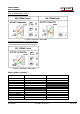
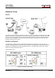
Adapter 3.5 mm to ¼” Headset output
adapter from remote remote radio
Adapter 3.5 mm to ¼” Paddle input adapter
to remote radio
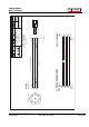
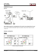
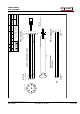
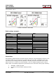
Control-RRC:
Connect the RS-232 cable Y5d between the Control-RRC COM2 and the CAT connector on
the Radio.
The microphone can be connected direct to the RRC AUX/MIC connector if you have a
microphone with RJ-45 connector. If you have a microphone with a circular connector use
the adapter cable Y5a.
The speaker is connected direct to the RRC SP-jack with a 3.5 mm stereo plug.
Paddles are connected to the PAD jack. If you the paddles have a ¼” plug on your paddle
use the supplied ¼” to 3.5 mm adapter cable.
Connect the CAT 5 cable from the Ethernet jack to your switch or router
Connect the 12V power supply to the DC jack
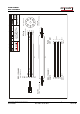
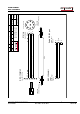
Radio-RRC:
Connect the RS-232 cable Y6d from the Radio-RRC COM2 connector to the radios CAT
connector.
Connect the mic cable Y6a from the Radio-RRC AUX/MIC connector to the radios
microphone jack.
Connect the speaker signal from the radios headset output jack or similar to the Radio-
RRC SP jack with the standard 3.5 mm – 3.5 mm cable with stereo plugs in both ends. If
the radio have a ¼” jack use the supplied adapter ¼”” to 3.5mm.
Connect keyer cable (standard 3.5 mm – 3.5 mm cable with stereo plugs in both ends)
from the Radio-RRC PAD jack to the straight key input jack on the Radio. If the radio have
a ¼” jack, use the supplied 3.5 mm to ¼” adapter.
Connect the CAT 5 cable from the Ethernet jack to your switch or router
Connect the 12V power supply to the DC jack