
User manual

USER MANUAL
m crob t
RRC-1258 MKII
Ba1258B_RemoteRig_MkIIs-A33.docx
Microbit 2.0 AB 2010. All rights reserved
a
User manual
Rev. A33 – 2015 Jan 28
78 of 236
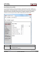
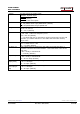
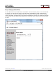
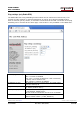
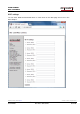
Parameter
Setting
OUT0 mode
Select the function for output-0 (OUT0) signal the I/O connector.
0 = I/O, active when IN0 on Control-RRC is active (Control-RRC IN0-mode
setting must be in state I/O). (default)
1 = Keyer, output to the radio straight key input
2 = PTT, used as external PTT
3 = Connect, active when the SIP-connection is active
4 = On/Off, controlled by the ON/OFF button on this side
(*)
5 = Keyer PTT, active when CW is send via the keyer (can be used to key
a PA). If you set “key delay” in the Control-RRC this output will be
activate “key delay” ms before the actual CW-keying is started.
6 = Baudot/45 used as output for RTTY 45.45 baud. RTTY input via USB
virtual com port at Control-RRC. Connect PC software to the virtual
com named FSK COM.
7 = Baudot/45 (inv) same as above but the RTTY key signal is inverted.
OUT1 mode
Select the function for output-1 (OUT1) signal the I/O connector (or tip in
the PAD-jack).
0 = I/O, active when IN0 on Control-RRC is active. (Control-RRC CW-
Keyer
function must be disabled). (default)
1 = Keyer, output to the radio straight key input
2 = PTT, used as external PTT
3 = Connect, active when the SIP-connection is active
4 = On/Off, controlled by the ON/OFF button on this side
(*)
5 = Keyer PTT, active when CW is send via the keyer (can be used to key
a PA). If you set “key delay” in the Control-RRC this output will be
activate “key delay” ms before the actual CW-keying is started.
6 = Baudot/45 used as output for RTTY 45.45 baud. RTTY input via USB
virtual com port at Control-RRC. Connect PC software to the virtual
com port named FSK COM.
7 = Baudot/45 (inv) same as above but the RTTY key signal is inverted.
OUT2 mode
Select the function for output-2 (OUT2) signal the I/O connector (or ring in
the PAD-jack).
0 = I/O, active when IN0 on Control-RRC is active. (Control-RRC CW-
Keyer
function must be disabled).
1 = Keyer, output to the radio straight key input. (default)
2 = PTT, used as external PTT
3 = Connect, active when the SIP-connection is active
4 = On/Off, controlled by the ON/OFF button on this side
(*)
5 = Keyer PTT, active when CW is send via the keyer (can be used to key
a PA). If you set “key delay” in the Control-RRC this output will be
activate “key delay” ms before the actual CW-keying is started.
6 = Baudot/45 used as output for RTTY 45.45 baud. RTTY input via USB
virtual com port at Control-RRC. Connect PC software to the virtual
com port named FSK COM.
7 = Baudot/45 (inv) same as above but the RTTY key signal is inverted.
(*)
When the ON/OFF buttons are pushed the output change will be immediate, but will
resume to last saved position after power on. To make the changes permanent use the "apply
changes" button.