
User manual

USER MANUAL
m crob t
RRC-1258 MKII
Ba1258B_RemoteRig_MkIIs-A33.docx
Microbit 2.0 AB 2010. All rights reserved
a
User manual
Rev. A33 – 2015 Jan 28
159 of 236
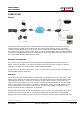
Connections
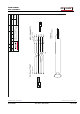
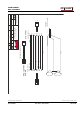
The cabling is quite simple and can be done with standard patch cables. Drawings of the
connection cables can be found below.
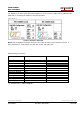
Control-RRC:
The control cable Y13a a standard RJ-45 patch cable should be connected between the
Control panel and the AUX/MIC connector.
The original microphone should be connected direct to the radio front panel as usual.
A pair of speakers are connected direct to the RRC SP-jack with a 3.5 mm stereo plug. A
set of amplified PC speakers will work very well also.
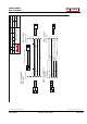
Radio-RRC:
The control cable Y14a a standard RJ-45 patch cable should be connected between the
Radio-RRC AUX/MIC jack and the Radio.
The speaker cable (Y14bc) eg. a standard cable with 3.5 mm mono connectors in both
ends should be connected between the radio and the Radio-RRC speaker jack.
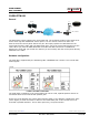
Power supply
Control-RRC:
The Control-RRC is supplied with a common 13,8 V (10-18V) power supply. The display and
speaker amplifier needs a lot of power so you need 1A.
Radio-RRC:
The Radio-RRC should be supplied from the same power supply as the radio to avoid
humming. Please put a small fuse on the cable if you connect it to a 30 Amp PS.