
User manual

USER MANUAL
m crob t
RRC-1258 MKII
Ba1258B_RemoteRig_MkIIs-A33.docx
Microbit 2.0 AB 2010. All rights reserved
a
User manual
Rev. A33 – 2015 Jan 28
109 of 236
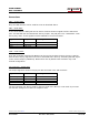
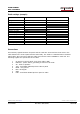
Radio settings (example)
Parameter
Control
Radio
Program mode
2 – IC-7100/IC-706/IC-703
2 – IC-7100/IC-706/IC-703
SIP password
hello
hello
SIP contact
192.168.0.228
Auto connect
No
Audio quality
2 – Linear 16 bits 8 kHz
2 – Linear 16 bits 8 kHz
Audio dual-rx (*)
No
Codec out gain
255
255
Codec inp gain
18
0
Codec inp preamp
Yes
Codec inp HPF Hz
163
163
COM0 baudrate
38400
38400
COM0 data bits
8
8
COM0 stop bits
1
1
COM0 parity
0 - Off
0 - Off
(*) Available only in RRC-1258MkIIs.
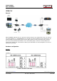
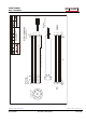
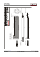
Connections
All necessary signals between the panel and the radio are connected via the 8 wires in the
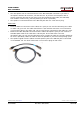
cable between the control panel and the radio body. The cable is a standard CAT-6 shielded
patch cable. We just need to add one cable and connect a RRC-1258MkII in each end. The
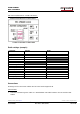
following signals are represented in the cable.
1 8V power to control panel (only when radio is ON)
2 PWR SW - power switch, grounding it switch on the radio
3 AF - audio to speaker.
4 TXD - serial data 38400 bps from radio to panel
5 MICE - mic ground
6 MIC- mic Signal
7 GND
8 RXD - serial data 38400 bps from panel to radio