Owners Manual Installation Guide Version 2012.07.12 microHD - Digital Video Recorder Ready Congratulations on your purchase of a quality GEOSATpro product, the microHD! This manual contains basic operation and installation instructions for the microHD satellite receiver with digital video recording capability. If you have any programming or operation questions, please contact your reseller for primary support.
Table of Contents Page FCC Notice and Compliance Important Safeguards 2 3 microHD Features and Specifications Receiver Front / Rear Panel Remote Control Layout Basic Remote Operation 5 8 9 8 Installation Guide Parts List Site Survey Dish Mounting Options LNBF Installation Dish Aiming Connect Receiver to a TV microHD Install Menu Setup Locate and Peak Satellite Signal Completing the Install and Grounding
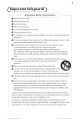
FCC Notice DTV Transition Notice: After June 12th, 2009, a television receiver with only an analog broadcast tuner will require a converter box to receive full power over-the-air broadcasts originating from a United States broadcaster with an antenna because of the Nation’s transition to digital broadcasting.
Important Safeguards www.geosatpro.
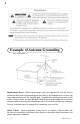
Example of Antenna Grounding NEC, ANSI/NFPA 70 Replacement Parts When replacement parts are required, be sure the service technician has used replacement parts specified by the manufacturer or have the same characteristics as the original part. Unauthorized substitutions may result in fire, electric shock, or other hazards. Modification to the hardware or software without authorization by the manufacturer the will result in voiding any warranty.
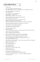
microHD Features • • • • • • • • • • • • • • • • • • • • • • • • Full HD 1080P Fully compliant MPEG-2 MP@HL & MP@ML Fully compliant MPEG-4 H.264/AVC Main Profile Level 3 & High Profile Level 4.1 Fully compliant MPEG-1 Layer I & II & III VCM / MIS Capable SCPC & MCPC from C/Ku Band Satellites USALS/DiSEqC 1.2 Motor Control 22KHz/DiSEqC 1.0/DiSEqC 1.
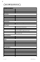
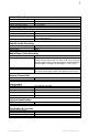
microHD Specifications Sheet1 Chipset and Memory Main Processor CPU Flash RAM Operating System Capacities Satellites Transponders Channels Favorites Timers Electronic Program Guide (EPG) Front Panel LED Status IR Sensor Rear Panel LNB IN HDMI RCA Video Audio USB 2.
Sheet1 Switch / Motor Control 22K Tone Frequency DiSEqC Control DiSEqC 1.2 Positions USALS Calculation Range Satellite Video Decoding Video Compression Support Aspect Ratio Video Resolutions - HDMI Video Resolutions - Composite Satellite Audio Decoding Audio Compression Support Audio Modes Sample Rates 22KHz; 0.4 - 0.9V DiSEqC 1.0, 1.1, 1.2, USALS 99 +/- 70 degrees MPEG-1㸪MPEG-2㸪H.
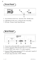
Front Panel 1 Power Indicator LED: Green - Operation / Red - Standby mode 2 USB Indicator LED: Green - Connected / Red - Recording 3 IR Sensor - Remote Control Signal Receptor Rear Panel Connect the satellite dish LNBF coax cable to Satellite IN Connects composite VIDEO and L/R Audio to TV or other equipment Connects HDMI Video Audio to TV or other equipment Connects USB 2.
Remote Control Unit 15 16 17 18 19 20 21 22 23 24 25 26 27 28 29 30 1 Select Standby or Operation Mode 2 3 4 5 6 7 8 Display Signal Meter Select the Favorite Channel List Mode Display Electronic Program Guide Display the Main Menu Screens Change Channels or Navigate the Menu Increase / Decrease the Volume Select Alternative Language / Audio Mode or Sound Tracks 9 10 11 12 13 14 Select Closed Caption On/Off Return to Last Channel Magnify an Area of the Screen Mute or Enable Audio Select Satellite f
10 Basic Remote Operation Turn the microHD On or Off using the POWER button. Change channels by entering the channel on the numeric keypad or by pressing UP/DOWN keys. Press the PREVIOUS CHANNEL key to return to the last channel. Select to view TV or to listen to Radio by pressing the TV/Radio key. Adjust the volume by pressing the VOLUME UP/DOWN key. Volume is also controlled by the TV. Mute the volume by pressing the MUTE key. Return to normal volume setting by pressing MUTE or the VOLUME UP/ DOWN key.
11 Installation Guide Save all original boxes, manuals, accessories and packaging materials in case it is necessary to return the merchandise. Before unpacking, assembly or operation of any item, review the reseller’s warranty, exchange and refund policy. This guide is intended for an individual experienced in performing the various tasks described, including: • Determining an antenna location with a view of the satellites positions. • Climbing a ladder and working on your roof.
12 Free To Air System Parts List Installation Kit Satellite Receiver Tools Required Socket Set Drill and Bits 90cm Dish and LNBF Phillips Screwdriver Hammer Tape Measure Site Survey If you feel comfortable with drilling holes in the walls and/or roof of your home, climbing ladders, attaching wires to the ground according to NEC and local codes and following step-by-step instructions, you might consider installing your own system.
13 Where Are The Satellites? Before assembling any equipment it is important to verify that the installation location has a suitable area to safely and securely mount the satellite dish and have a clear line of site to receive the satellite signal. The satellite dish must be pointed directly at the satellite, with NO obstructions between the two. This means NO trees and NO buildings.
14 Please note: 97W is not the compass reading! 97W is the assigned orbital slot which corresponds with the earth’s Longitude. The Galaxy 19 satellite is just east of DirecTV’s main satellite at 101W. Target Satellite Compass (Azimuth) Reading: _____________ How High Up in the Sky are the Satellites? Depending on where you live, most North American satellites will be at an elevation angle between 30 and 60 degrees in North America.
15 Sight along the top edge of the elevation angle finder with the weighted string registering the correct elevation angle for your target satellite. Is the line of sight clear with no branches, limbs or tall buildings? Elevation Angle Finder If you are mounting your dish on a motor, consult with the motor installation manual for recommendations on dish placement and mounting. Be sure to perform a site survey to determine the best location to see as many satellites as possible.
16 Wall Mount Roof Mount The GEOSATpro 90cm dish assembly includes a heavy duty universal wall / roof post mount. This mount can be attached at almost any angle and provides a stable secure mount even in high wind regions if properly attached. The tripod legs MUST be installed. The universal post will fail under moderate wind load if the tripod legs have not been installed to support the larger wind load area of a 36” dish.
17 Fixing a Warped Reflector To correct a warped reflector, hold the dish like a steering wheel and quickly thrust the reflector away from your body like the motion of passing a basketball. This quick action will cause the reflector to slightly flex and spring back into the factory pressed shape. Check for correction with the string test. It may be necessary to repeat the flexing process several times until the reflector edges are uniformly flat.
18 Dish Aiming When setting the elevation angle on an offset dish, it is important to note that the dish will appear be aimed lower than the actual elevation angle to the satellite. The scale on the elevation bracket is calibrated for accurate aiming when the post is installed perfectly plumb (leveled on all sides). The dish elevation angle is not set by the angle of the LNBF arm or face of the dish.
19 Identify a reference point on the horizon like a tree, utility pole or other landmark that lines up with the compass reading. Installers often find it easier to align the dish if they can reference an object that has been identified with the compass reading. If you cannot locate a visual reference, stretch a 10 - 20 foot rope out in front of the dish in the direction of the compass reading pointing towards the satellite.
20 A basic connection for standard definition SD TV viewing is to connect the to the TV with the included AV cable. Place the 1/8th inch plug into the receiver’s AV Out port and connect the yellow/white/red RCA plugs to the TV’s AV IN jacks. To view high definition video in HD, connect a HDMI cable between the receiver and TV. Plug the television power plug into a surge protected AC power strip. Turn the TV power ON and set the TV to the AV input. The TV is now ready to view the satellite receiver.
21 microHD Installation Menu Setup To receive Free To Air (FTA) programming, the receiver menus must be configured and the dish aimed for the satellite that you wish to receive and for the satellite equipment that is connected. Before programming the receiver you will need to know what satellite carries the channels that you wish to receive. If you do not know the name of the satellite, visit www.lyngsat.com for a list of satellites and the available channels.
22 6. The one activated satellite will be displayed. Press the Down arrow to highlight Transponder. Press OK to list the Pre programmed transponders. 7. Highlight the target transponder using the UP / Down navigation arrows. Press OK to select. An active transponder (TP) must be selected in order to detect a satellite. Failure to select an active transponder will result in no satellite being found. 8. Highlight LNB LO using the UP / Down navigation arrows.
23 Meter Readings This meter displays a reading for a receiver that is not properly connected to the dish LNBF or a menu setting is incorrect. A Signal Level reading of 0% could indicate that there is bad connection between the receiver and the LNBF. Verify that a coax cable is directly attached from the SAT IN port on the rear of the satellite receiver to the LNBF on the satellite dish. A Grey color Signal Level reading of 45% or better indicates that the receiver is connected to a working LNBF.
24 Example of Low Signal Quality reading that might be displayed as the satellite signal is found, but aiming is not optimized. 12. Continue to optimize the dish aiming by making very small changes to the elevation (up/down) and azimuth (left/right) to peak the Signal Quality reading. Failure to optimize and maximize the Signal Quality reading may result in the loss of programming during inclement weather. Example of optimized Signal Quality reading when dish aiming is correct.
25 16. Highlight Scan Mode. Press the LEFT or Right navigation arrow to select either to scan the satellite by using the Pre programmed TPs (transponders) list, Blind Scan - Normal to search the entire satellite for new transponders and channels at a normal speed or Blind Scan - Detailed to search the entire satellite for new transponders and channels at a slower speed with more detail and accuracy. For this example scan, use Pre programmed TPs mode. 17. Highlight Symbol Rate.
26 Completing the Install and Grounding Carefully route the coax cable from the dish to the ground block then to the satellite receiver. Secure all cables using appropriate cable clips and nylon zip ties. Avoid using wire staples as they can dimple or penetrate the cable and can cause loss of signal! Form drip loops and cable loops as needed to prevent water from running down the cables and entering cable connection fittings or into wall penetrations.
27 Receiver Features Channel Information The channel banner appears at the bottom of the TV screen and provides basic channel information about the displayed after each channel change. Press the INFO key to recall the display. Press INFO key two times to display extended technical information. Press EXIT key to remove the display. TV or Radio The microHD receives both TV and Radio stations. Press TV/RADIO key to select either TV channel or Radio stations.
28 Channel Lists To display the Channel List of saved channels, press LIST/OK key If connected to a Multi Satellite System - Press LEFT or RIGHT NAV key to select a satellite Press UP or DOWN NAV key to highlight a new channel Press OK key to go to the channel. Press OK key a second time or press EXIT key to remove the Channel List display To search the Channel List for a specific channel, press the RED color key. Press LEFT or RIGHT NAV key to select a character of the channel name and press OK key.
29 Electronic Program Guide - EPG The Electronic Program Guide service provides schedule information about the current and upcoming programs. Only a few Free To Air broadcasters in North America provide this service. When available, EPG greatly enhances the viewers experience. Know in advance when a program will be airing and easily schedule DVR recordings. If the Channel Banner displays the EPG icon and program information is displayed, the EPG service is available on this channel.
30 Setting an EPG Timer Timers may be set to tune a channel at a selected time or to Record the program for future viewing. This example is for setting a DVR recording. Note: A USB drive must be connected to the microHD to enable the DVR recording function. Highlight the program to record then press the GREEN color key to set a timer. Press LEFT or RIGHT NAV key to select Once Press DOWN NAV key to highlight Timer Service Press LEFT or RIGHT NAV key to select Record Press DOWN NAV key to highlight Save.
31 Audio or Language Selection Often a channel may transmit several audio choices and the viewer may select between standard, Dolby, multiple languages or select a mono, stereo channel.
32 Zoom Function The zoom key magnifies and enlarges a portion of the screen in steps of 2x, 4x, 6x, 8x, 12x and 16x settings. Press ZOOM key to activate Repeat pressing Zoom key to increase the magnification Press LEFT/RIGHT/UP/DOWN NAV keys to select the area of the screen to magnify. Press EXIT key to return to normal viewing. Receiver Menu Items Main Page To enter the microHD Menu screens, press MENU key. Five Sub Menu icons will appear on the left side of the screen.
33 1.1 / 1.2 TV or Radio Channel List Press LEFT or RIGHT NAV key to select the satellite, All Satellites or Favorites List. Press UP or DOWN NAV key to select a channel. Press OK key to preview.
34 Press Exit several times to display “Confirm Save”. If you wish to save the changes, select Yes and press OK key. To exit without saving changes, select No and press OK key. Lock – Parental Control Password Press the RED color key to select the function to add or delete channels that are unavailable unless the Parental Password is entered. The Lock tab will pop up when this function is selected.
35 Press UP or DOWN NAV key to highlight a channel to skip Press OK key to select Press OK key to alternate between displaying a skip icon to indicate that the channel will be skipped over or no skip icon displayed indicates that the channel will be available. Press UP or DOWN NAV key to select additional channels skip or make available Press Exit several times to display “Confirm Save”. If you wish to save the changes, select Yes and press OK key. To exit without saving changes, select No and Press OK key.
36 Lock – Channel List starts with Parental Lock protected channels Polarity (H-V) - Channel List starts with channels on horizontal transponders then vertical transponders Polarity (V-H) - Channel List starts with channels on vertical transponders then horizontal transponders Edit – Channel Rename Press the GREEN color key to select the function to rename channels. The Edit tab will pop up when this function is selected. Type the new name using the numeric keys.
37 1.3 Delete All Channels - TV & Radio Press OK key to delete all TV and Radio Channels. If you wish to delete all channels, select Yes and press OK key. To exit without deletion, select No and Press OK key 1.4 Save as Default The receiver can be restored to a default profile by performing a Factory Reset. Save as Default makes the current the Satellite list (including motor and switch settings), Channels list, Favorites lists to be the new default file.
38 Press OK key to alternate between displaying a heart icon to indicate that the satellite has been activated to make available for Motor/Switch Set-up and Channel Searches. No heart icon displayed indicates that the channel is not activated and available for Motor/ Switch Set-up and Channel Searches. Rename Existing Satellite or Change Orbital Position Press UP or DOWN NAV key to highlight a satellite Press the RED color key Type the new satellite name using the numeric keys.
39 The orbital position is referenced by the USALS calculation and motor positioning program, highlight Longitude and press LEFT or RIGHT NAV key for East or West orbital position. Use the numeric keypad to enter the satellite’s orbital position. YELLOW color key accepts changes to the satellite name and/or position, BLUE color key cancels. Delete Satellite Press UP or DOWN NAV key to highlight the satellite to delete from the Default Satellite List.
40 Transponder (TP) - A list of pre programmed transponders is available for each satellite. Press LEFT or RIGHT NAV key or press List/OK key to display scroll list. If the target transponder is not displayed, go to TP List 2.5 and add a transponder. Note: An active transponder must be selected for the target satellite, Failure to select an active transponder will result in no valid signal for locating and identifying the satellite. You may find a list of satellites and active transponders at www.lyngsat.
41 DiSEqQ 1.1 – Switch Setting. If multiple satellite dishes or multiple LNB(f)s are connected to your receiver (up to 16 inputs), determine if the switch type is DiSEqC 1.1. If so, press LEFT or RIGHT NAV key or press List/OK key to display scroll list. Select the switch port that is connected to the target satellite. 22KHz – Switch Setting. If a Universal type LNBF is used, the 22KHz switch setting will be automatically set to AUTO and a 22KHz switch is not used due to switching control conflicts.
42 USALS Motor Type - With USALS selected, Press OK key Use LEFT or RIGHT NAV key to select if the install location’s Longitude is East (E) or West (W). North America is typically referenced as the western hemisphere so select W. Use the Numeric keys to enter the install location’s Longitude as xxx.xx. Press UP or DOWN NAV key to select Local Latitude. Press LEFT or RIGHT NAV key to select if the install location’s Latitude is North (N) or South (S).
43 Press LEFT or RIGHT NAV key or press List/OK key to display scroll list. Select a motor position number (1 – 99) to save the satellite position both the microHD and in the motor memory or controller memory. The motor position will be saved to this assignment number in order for the receiver to communicate with the motor to return to the a specific position. Multiple satellites may be assigned to the same motor position number. Example C and KU band bands of the same satellite position.
44 Go to X – Drive the motor to the Reference 0 (zero) position or to any saved DiSEqC 1.2 motor position assignments. Press UP or DOWN NAV key to select Local Latitude. Press OK key and motor will drive to the saved satellite position. Recalculate – Allows the user to assign new offset 0 (zero) reference for motor control center point. Highlight Recalculate and press OK key. To clear and set a new 0 (zero) reference position, select Yes and press OK key.
45 2.2b Limit Setup Set East/West Motor Limits Prevent damage to the motor or the dish. Set a limit on the distance that the motor travels to avoid hitting any object if the motor is allowed to rotate too far.
46 Setting West Limit Press UP or DOWN NAV key to highlight Limit Set-up Press RIGHT NAV key to select East Limit Press UP or DOWN NAV key to select While watching the motor, drive the motor towards the East using RIGHT NAV key and release to stop the movement before striking any object or reaching the maximum physical limit of the motor rotation Press OK key to save limit Move Motor to Reference Position Press UP or DOWN NAV key to select Press OK key to move the m
47 Network Search – Scans the Network Information Table and logs any services that the uplinker identified. Note: Active only when scanning pre programmed transponders.
48 Blind Scan - Normal or Detailed: Scan Frequency Range menu allows the user to change the default settings and define the start and stop frequency range to log new transponders and channels. Highlight Frequency Start and use the numeric keys to enter the start frequency. Press UP or DOWN NAV key to highlight Frequency Stop and use the numeric keys to enter the stop frequency. The available start/ stop frequency range will be defined by the LNB that is connected. If the LNBF states 11.7 – 12.
49 2.4 Multi Satellite Search Search multiple satellites with a motorized or switched multiple satellite system. See Single Satellite Search Description (2.3). All functions are identical to those in the Single Satellite Search with an additional function allowing the microHD to automatically control the switches and/or motors to scan multiple satellites. The scan will search the list of Activated Satellite List (2.1). A list of satellites to be scanned is displayed at the bottom of the menu screen.
50 Edit TP Modify Existing Transponder Frequency, Symbol Rate, and Polarity Press the RED color key Type the new Frequency using the numeric keys Press UP or DOWN NAV key to highlight Symbol Rate Type the new Symbol Rate using the numeric keys Press UP or DOWN NAV key to highlight Polarity Press LEFT or RIGHT NAV key to select either Horizontal (Left) or Vertical (Right) Press UP or DOWN NAV key to highlight Save or Cancel. To save the modified TP, select SAVE and press OK key.
51 Delete Transponder Press UP or DOWN NAV key to highlight the transponder to delete from the Pre programmed TP List. Press the YELLOW color key Press LEFT or RIGHT NAV key to select Yes to delete only the selected TP or Del All to delete all transponders from the selected satellite. Press Exit several times and a prompt appears requesting a confirmation to delete. If you wish to delete the TPs, select Yes and press OK key. To exit without deleting the transponders, select No and Press OK key.
52 Press UP or DOWN NAV key to highlight Network Search Press LEFT or RIGHT NAV key to Yes or No Press UP or DOWN NAV key to highlight OK or Cancel. If you wish to scan the TP for new channels, select OK and press OK key. To exit without searching, select Cancel and Press OK key PID Mode - Manual Channel Entry Press UP or DOWN NAV key to highlight Video PID Use Numeric keys to manually enter the Video PID.
53 Scan Results When the scan is complete the Transponders scanned, and logged TV and Radio channels will be displayed with a prompt “ Search End” or “No Program Found” Press OK key to exit the Search screen 3. System Setup 3.1 Language 3.2 TV System 3.3 Display Setting 3.4 Local Time Setting 3.5 Timer Setting 3.6 Parental Lock 3.7 OSD Setting 3.8 Favorite 3.9 Other 3.
54 Subtitle Language: Default Subtitle text language automatically selected if broadcaster provides Subtitle Service and in multiple languages (see language selection above). Typically not used in North America. Teletext: Default Teletext text language automatically selected if broadcaster provides teletext service and in multiple languages (see language selection above). Typically not used in North America. 3.2 TV System Video Resolution: Setting the Output Resolution for HDMI Video.
55 Bitstream: No AC3 decoding. Raw AC3 to HDMI output LPCM: Decodes both PCM and AC3 for output to HDMI output The RCA audio outputs always are fed decoded AC3 and PCM. 3.3 Display Setting: Adjustments for Composite and HDMI Video Outputs. Press LEFT or RIGHT NAV key or press List/OK key to display scroll list. Select new level and it is immediately applied. Brightness, Contrast, Saturation, Hue and Sharpness 3.
56 3.5 Timer Setting with Remote Control Short Cut Key: Thirty timers wake-up the microHD, return to standby mode, change channels, start and stop DVR recordings. Press UP or DOWN NAV key to highlight available timer. Press OK key to display Timer Setting menu with current time and date displayed in upper right corner. Press UP or DOWN NAV key to highlight Timer Mode Press LEFT or RIGHT NAV key to select frequency of the timer event.
57 Press UP or DOWN NAV key to highlight Save or Cancel. If you wish to schedule the timer, select OK and press OK key. To exit without saving the timer setting, select Cancel and Press OK key Notice: If the microHD is in standby mode when timer is scheduled, the receiver will automatically Power ON one minute before the Start Time.
58 Use the numeric keys to re-enter the four digit code. A prompt will confirm the updated Password. Press OK key to exit 3.7 OSD Setting: Settings for Subtitle, Teletext and OSD (On Screen Display) Subtitle Display: Press LEFT or RIGHT NAV key to select On or Off. Typically not used in North America. OSD Timeout: Press LEFT or RIGHT NAV key or press List/OK key to display scroll list.
59 3.9 Other: Functions Setting additional LNB Power: Press LEFT or RIGHT NAV key to select if the LNB power is On or Off. Typically this will be On, but might be set to Off if the receiver is slaved.
60 4.2 Factory Reset: Press OK key to perform a Factory Reset. Warning this will reset all settings to default. All user settings will be lost. Be sure to save firmware, backgrounds and user data to an external USB if you wish to save the receiver settings, user added satellites, transponders, channel and favorites lists. Press UP or DOWN NAV key to highlight Yes or No. If you wish to delete all user data and return the receiver to default settings, select OK and press OK key.
61 4.5 Update by USB: Update Firmware, Background Images, Default and User Database profiles including satellites, transponders, channels and favorites lists.. Caution: Before Updating, first backup and Save to USB (see 4.6), the User Data Base .udf file or Default Data Base .ddf to restore customs settings such as: menu settings, background images and default or user database profiles.
62 4.
63 Press LEFT or RIGHT NAV key to highlight Yes or No. If you wish to disconnect the USB, select Yes and press OK key. To exit without disconnecting the USB, select No and Press OK key Press LEFT or RIGHT NAV key or List/OK key to display a list. Select the USB drive to disconnect (the default is USB Disk A) Press UP or DOWN NAV key to highlight OK or Cancel. . If you wish to disconnect the selected USB, select OK and press OK key. To exit without disconnecting the USB, select Cancel and Press OK key 5.
64 Play List: Manage and play the audio files selected as favorite: OK key = Play files in Play List, RED key = Move, GREEN key = Delete, YELLOW key = Delete All Edit: Edit the audio files: Red key = Rename, Green key = Copy, Yellow key = Delete, Blue key = Create New Folder Sort: Sort audio files by: Name, Time, Size or Favorite How to Listen to an Audio File: Press DOWN NAV key to select the connected USB drive Press OK key to show available music files Press UP or DOWN NAV key to highlight a photo (Pr
65 Image Mode: Display one photo at a time or create a playback list.
66 How to Watch a Video File: Press DOWN NAV key to select the connected USB drive Press OK key to show available video files Press UP or DOWN NAV key to highlight a video (Preview displays file information) Press PLAY key to play the video file in the Preview display Press OK key to Play in full screen mode Pause, step frame, multi-speed reverse/forward, play and stop keys are available for control.
67 5.2 DVR USB Memory Information Provides file information for the connected USB drive. 5.3 DVR Set-up: Feature Setting for DVR Operation Press UP or DOWN NAV key to highlight Time Shift Press LEFT or RIGHT NAV key to select On or Off. On temporary records the current tuned channel. Timeshift allows the review of current channel programming that has been automatically recorded since the last channel change (maximum record time is two hours).
68 Press UP or DOWN NAV key to highlight PS Record Press LEFT or RIGHT NAV key to select: On or OFF. We recommend leaving PS (Program Stream) Off as the DVR often cannot record HD programs with PS Record On. USB Drive Formatting Warning! Formatting the USB drive will erase all recordings and files on the drive. You will not be able to undo this process. If you wish to archive the recordings or files before formatting, connect the USB drive to a computer and copy the files to another drive.
69 FAQ – Frequently Asked Questions Satellite receiver displays “Warning - Do NOT power off Software Download” for more than 1/2 hour. The satellite signal may have been interrupted during the automatic updating process. Reset Master Power switch on rear of the receiver. Place receiver on channel 1 and press the Signal button on the remote. If the Signal Quality is below 50% the receiver will not update and require dish adjustment.
70 may not have enough transfer speed to handle the DVR function. Make sure that the USB device is 2.0 type. Try another USB drive with better processing speed. Thumb drives often cannot process the data and the picture pixilates or freezes. Message window displays “USB Speed to low” when trying to record. The connected USB device may have limited throughput speed or be formatted incorrectly. Format drive to either NTFS or FAT and retry recording. Consult with the drive manufacturer.
71 Cut Here www.geosatpro.