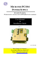
MICRONIX PC/104 POWER SUPPLY PV-5127, PV-5127A POWER SUPPLY MODULE WITH UPS & BATTERY CHARGER User Manual & Installation Guide VERS. 1.1 DOC: M5236DM Micro Technic A-S • Denmark • Tel. +45 6615 3000 • Fax +45 6615 3077 E-mail: support@micro-technic.com Website: www.micro-technic.
Users Manual & Installation Guide PV- 5127: Power supply module with UPS Table of contents TABLE OF CONTENTS ................................................................................................................................................. 2 REVISION HISTORY ..................................................................................................................................................... 4 GENERAL INFORMATION.................................................................
Users Manual & Installation Guide PV- 5127: Power supply module with UPS J1............................................................................................................................................................................. 28 ST3 .......................................................................................................................................................................... 28 J2..............................................................................
Users Manual & Installation Guide PV- 5127: Power supply module with UPS Revision history Revision number 1.0 1.1 Page 4 of 31 Reason for change Initial revision Error in mechanical layout changed – page 27.
Users Manual & Installation Guide PV- 5127: Power supply module with UPS General information Ordering codes PV-5127-S PV-5127A-S S=Stack-through PC/104 connector Available models: Model no PV-5127-S PV-5127A-S Description 75W PC/104 Power Supply Module (+5V, +12V), 18-35V input supply with UPS/Battery charger 75W PC/104 Power Supply Module (+5V, +12V), 10-35V input supply Accessories These accessories must be ordered separately if needed.
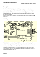
Users Manual & Installation Guide PV- 5127: Power supply module with UPS Description The Micronix PV-5127 is a high efficiency PC/104 power supply for embedded, vehicular and automotive systems applications. It will withstand extended temperatures and the shock and vibration of mobile equipment. Micronix PV-5127 has an input supply range of 18-35V (PV5127A: 10-35V), which is convenient for automotive and low-voltage applications.
Users Manual & Installation Guide PV- 5127: Power supply module with UPS The mains supply is continuously monitored. There is hysteresis on the mains monitor so that a mains failure is reported when the mains voltage drops below 16.5V, and mains is reported OK when the voltage rises above 17.5V. # $ % & $ ' () !" The connected lead-acid backup battery is maintained by an integrated battery charger (fast charge and trickle charge).
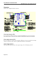
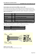
Users Manual & Installation Guide PV- 5127: Power supply module with UPS Connectors The PC-5127 is equipped with nine connectors: * * +, 8 * +, # * $* +, +, "- ( 777 !" * * * 34# 53 ' / / 6 1 ' ( -. # 0 1 2 /49 Power input connector (KL2) Power into PV-5127 (Mains and battery) is supplied through KL2 that is a four-pole removable screw clamp connector. The layout of this connector is printed in the silkscreen on the heatsink.
Users Manual & Installation Guide PV- 5127: Power supply module with UPS Heater and fan control and external LEDs connector (CN2) Status for PV-5127 can be shown on external LEDs. These must be connected to CN2 by a 10 position ribbon cable with a mating connector. Furthermore, the +5V Standby and logical outputs for the external heating element and the external fan are placed in this connector. The layout of this connector is shown in the schematic to the left of the connector.
Users Manual & Installation Guide PV- 5127: Power supply module with UPS ATX connector (CN10) The ATX connector holds the three ATX-signals: PS_ON, PWR_GOOD and +5V Standby. The layout of this connector is shown in the schematic.
Users Manual & Installation Guide PV- 5127: Power supply module with UPS PC/104 bus connector (CN1) The PC/104 connector is for connecting the PV-5127 to the CPU and other PC/104 boards. There is a female connector on the top, and pins on the bottom so that you can mount other PC/104 boards both above and below the PV-5127. The main +5V and +12V outputs are available in the PC/104 connector, so you don’t need to use the KL3 outputs when drawing smaller currents.
Users Manual & Installation Guide PV- 5127: Power supply module with UPS System temperature The PV-5127 has a temperature measuring circuit that can control an external fan and heater, and prevent the CPU from starting if the temperature is too low or too high. It monitors the system temperature as long as +5V STB is on. As system temperature sensor, you can use the onboard sensor, or an external sensor of type Infineon KTY 11-5 connected to J2 (labelled “Ext. sensor”).
Users Manual & Installation Guide PV- 5127: Power supply module with UPS Note that the heater and fan outputs are logical outputs that become 3.3V when they are active. If necessary, the user must provide driving circuitry to drive an actual heater and fan. The positions of the two outputs in CN2 are shown here. If the temperature is too cold or too hot, the CPU cannot be turned on until it changes to cool or warm.
Users Manual & Installation Guide PV- 5127: Power supply module with UPS UPS Control The PV-5127 provides several methods for the CPU to get UPS status information, and to turn off power. The CPU can get status information through the RS232 and the PC/104 interface, and it can perform a software-controlled power-off through the ATX PS_ON signal, through an RS232 signal, and through the PC/104 interface. PS_ON signal Two of the ATX functions that are supported in PV-5127 are: +5V STB and PS_ON.
Users Manual & Installation Guide PV- 5127: Power supply module with UPS RS232 The PV-5127 has a connector (CN3, labelled “RS232”) that can be connected to an RS232 port on the CPU. The PV-5127 provides two handshake outputs with status information, and one handshake input for controlling shutdown. The RxD and TxD signals are not used, the only used signals are Ground and the three handshake signals.
Users Manual & Installation Guide PV- 5127: Power supply module with UPS RS232 Status signals The Battery low and Mains failure signals together can tell three different states: Mains failure Battery low 1 1 0 1 Status 0 0 Running normally on mains power. Mains alarm, running on battery. The CPU is advised to shut down if mains power doesn’t come back within reasonable time. This time should be configured in the UPS monitoring software. Critical alarm. The CPU is advised to shut down immediately.
Users Manual & Installation Guide PV- 5127: Power supply module with UPS PC/104 interface The PV-5127 has a software interface where the CPU can read status information and perform a power-off through the PC/104 bus. The power-off can be delayed up to 253 seconds, so that the UPS monitoring can start the delayed power-off, then start a shutdown of the operating system, and the actual power-off happens after the operating system has finished shutting down.
Users Manual & Installation Guide PV- 5127: Power supply module with UPS b (STATUS bit 3): Battery present. b=0: Battery not present (empty or disconnected) b=1: Battery present BAT_STATUS (port 252h, read only): nn0cctvv This port contains the following read-only battery status information bits. vv (BAT_STATUS bit 1-0): Battery voltage. See the section Battery monitor and charger.
Users Manual & Installation Guide PV- 5127: Power supply module with UPS 00h: SOFT_OFF (first half of 2-second delay) FEh: SOFT_ON FFh: SOFT_OFF (second half of 2-second delay), or SOFT_TEMPBAD Other values: SOFT_DELAY, delayed shutdown in progress. value = remaining seconds until SOFT_OFF Software normally won’t read the values 00h and FFh since the 5V+12V is off at this time. Writing 00h will turn off power immediately, and it will stay off for at least two seconds.
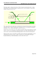
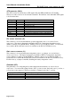
Users Manual & Installation Guide PV- 5127: Power supply module with UPS Battery monitor and charger Battery voltages The PV-5127 monitors the voltage of the battery as long as the main DC/DC converter is on. The voltage status controls the charger, the RS232 alarm output, the battery LED, and it can be read through PC/104. The possible ranges are: Range Empty Low Medium Full Disconnected Thresholds Below 9.5V Between 9.5V and (10.75V, 11.25V) Between (10.75V, 11.25V) and (13.0V, 14.7V) Between (13.
Users Manual & Installation Guide PV- 5127: Power supply module with UPS mounted directly on the battery. The charging is disabled when the temperature according to this sensor rises above 55°C, and enabled when it falls below 45°C. The J1 input has the following function: Installed on J1 Charger function Nothing A jumper A KTY11-5 sensor Disabled. See note.
Users Manual & Installation Guide PV- 5127: Power supply module with UPS ATX and Softoff state machines The PV-5127 provides several ways to turn on/off power. ATX compatible CPUs can turn themselves on and off using PS_ON, and UPS monitoring software on CPUs without PS_ON can turn off using either a RS232 handshake signal or a software command through the PC/104 bus.
Users Manual & Installation Guide PV- 5127: Power supply module with UPS The ATX on/off state machine The ATX on/off state machine has two states: ATX_OFF and ATX_ON. Only in the ATX_ON state can the 5V+12V outputs be turned on. The state machine is controlled by the PS_ON input (located in the CN10 connector), and the system temperature status. PS_ON is active low – it is active when pulled low to 0V, and inactive when high or left floating.
Users Manual & Installation Guide PV- 5127: Power supply module with UPS It can be illustrated like this: . ( ' (7 $( ( 3 :4; "!/< 1 ( 3 :4; , . ( 3 :4;4" .#/ • • • • • $ $( ' (7 ( 53 ( $ - ( 45 ( $ - ( 3 :4; :: ( ( $ The state machine starts up in SOFT_TEMPBAD when the main DC/DC converter starts. In this state, the 5V+12V cannot be turned on. It stays in this state as long as the system temperature is too cold or too hot. SOFT_ON: This is the normal “on” state.
Users Manual & Installation Guide PV- 5127: Power supply module with UPS Technical data Power supply: Input voltage: PV-5127-S: PV-5127A-S: Output Voltage 1: Ripple/noise: Line regulation: Load regulation: Output Voltage 2: Ripple/noise: Line regulation: Load regulation: Output Voltage 3: Output power: Efficiency: Overload protection: UPS/Battery Charger: Battery type: Lead Acid charge: Battery protection: Temperature control: ATX signals: “RS232” Interface: Handshake signals: High temperature ala
Users Manual & Installation Guide Environmental specifications: Operating temperature: Storage temperature: Humidity: Cyclic humidity: Vibration: Sustained vibration: Shock: Size: (W x L x H): Page 26 of 31 PV- 5127: Power supply module with UPS -20°C to +70°C at 0.5 m/s airflow -40°C to +85°C 20 to 90% non-condensing ETS 300 019-2-5 or equal 10-1000 Hz sinus and random @ 1-1.
Users Manual & Installation Guide PV- 5127: Power supply module with UPS Mechanical layout The schematic on this page shows the dimensions for PV-5127. All dimensions are in mm.
Users Manual & Installation Guide PV- 5127: Power supply module with UPS Installation guide Precautions to ESD Please note that the Micronix PV modules must be handled with respect to ESD (Electrostatic Discharge). Electrostatic Discharge to the PV modules must be avoided. Before removing the module from the protection bag, the user must be discharged using a grounded wrist ribbon. Settings and connections ST1 To set the fast charge current to 1A, install a jumper at ST1 (factory default).
Users Manual & Installation Guide PV- 5127: Power supply module with UPS KL2 Connection of mains and battery voltage are made via KL2 as shown in the table: Connection in KL2 Function 1 2 3 4 Mains+ in Mains- in Battery- in Battery+ in Connect mains input to pin 1 and 2. To use a lead-acid backup battery, connect it to pin 3 and 4, otherwise leave pin 3 and 4 unconnected. To use a NiMH (Nickel Metal Hydride) battery for backup, a Micronix PV-1075 can be integrated in the PC/104 stack.
Users Manual & Installation Guide PV- 5127: Power supply module with UPS Thermal considerations When installing the Micronix PV-5127 in a PC/104 stack, some considerations about convection must be made. For the power supply to work properly, certain temperature limits must not be exceeded.
Users Manual & Installation Guide PV- 5127: Power supply module with UPS Differences between PV-5127 and PV-5127A The PV-5127 is available in a version without UPS and battery charger. The ordering code for this product is PV-5127A. These things are different in this version: • • • • • The mains voltage range is nominally 10-35V instead of 18-35V. The mains monitor reports mains failure at mains voltage below 9.0V and mains OK at above 9.5V, instead of 16.5V and 17.5V, respectively.