MICRONIX PC/104 DIGITAL IN-/OUTPUT BOARD PV-1648 64 CHANNEL DIGITAL I/O 16 DIGITAL INPUTS 48 DIGITAL OUTPUTS User Manual & Installation Guide VERS. 1.04 DOC: M5097DM.DOC Micro Technic A-S • Denmark • Tel. +45 6615 3000 • Fax +45 6615 3077 E-mail: support@micro-technic.com Website: www.micro-technic.
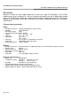
Users Manual & Installation Guide PV- SERIES: 16 DIGITAL INPUTS, 48 DIGITAL OUTPUTS DESCRIPTION Micronix PV-1648 lets you handle combined I/O from one single PC/104 board. The PV-1648 module plugs into any standard PC/- 104 bus interface and provides you with 16 digital opto-isolated inputs and 48 NPN non-isolated open collector digital outputs (optional pull-up to +5V). Non-Stackthrough or stack-through (S-versions) connectors are available. Supplied with drivers for Windows 95/98 and NT.
Users Manual & Installation Guide PV-SERIES 16 DIGITAL INPUTS, 48 DIGITAL OUTPUTS MODEL SELECTION PV - 16 48 - /PX - /5 - /S Number of digital inputs Number of digital outputs Pull-up resistors on outp.[x=KΩ] Pull-up to +5V internal S=Stack-through EXAMPLE: PV-1648 with PC-104 Non-Stack-through connector. PV-1648 - P1 - S with PC-104 Stack-through connector and 1K pull-up resistors on outputs.
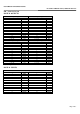
Users Manual & Installation Guide PV-SERIES 16 DIGITAL INPUTS, 48 DIGITAL OUTPUTS REGISTER FORMAT AND DESCRIPTION The PV-1648 occupies 8 consecutive addresses of PC I/O address space. The first address or base address is determined during installation by setting the onboard rotary address switch SW1. The registers and their functions are listed in the following table (R = Read, W = write and Base = Base address.
Users Manual & Installation Guide PV-SERIES 16 DIGITAL INPUTS, 48 DIGITAL OUTPUTS Software example: /* Compiler: Borland C++ 3.1 */ #include #include
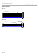
Users Manual & Installation Guide PV-SERIES 16 DIGITAL INPUTS, 48 DIGITAL OUTPUTS OPTIONAL CABLES, 30CM INPUT CABLE DSUB-25 female 26p. header female 26-way ribbon cable Pin1 OUTPUT CABLE DSUB-15 female 16p.
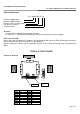
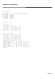
Users Manual & Installation Guide PV-SERIES 16 DIGITAL INPUTS, 48 DIGITAL OUTPUTS I/O – connector layout DIGITAL OUTPUTS CN3 digital output 0-11 Pin no: PV1648 & DSUB15F Function: 1 9 2 10 3 11 4 12 5 13 6 14 7 8,15,(16) Common /DO00 /DO01 /DO02 /DO03 /DO04 /DO05 /DO06 /DO07 /DO08 /DO09 /DO10 /DO11 Gnd CN2 digital output 12-23 Pin no: PV1648 & DSUB15F 1 13 6 14 7 9 2 10 3 11 4 12 5 8,15,(16) Function: Common /DO12 /DO13 /DO14 /DO15 /DO16 /DO17 /DO18 /DO19 /DO20 /DO21 /DO22 /DO23 Gnd CN4 digital outpu
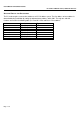
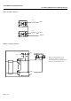
Users Manual & Installation Guide PV-SERIES 16 DIGITAL INPUTS, 48 DIGITAL OUTPUTS INPUT CIRCUITRY SCHEMATIC OUTPUT CIRCUITRY SCHEMATIC $ !%% - $ + , + , $ !% %% $ &'( )* When powering inductive loads, catch diodes must be connected across the loads to protect the output transistors on the PV1648 card.