
Specifications


Table Of Contents
- Content
- Welcome!
- Warranty
- 1. Getting Started
- 2. Software Configuration
- 3. Data Capturing
- 3.1. Open Files
- 3.2. Replay of Files
- 3.3. Editing Video Sequences
- 3.4. Saving Files
- 3.4.1. Setting the Recording Frame Rate
- 3.4.2. Setting the Recording Modes
- 3.4.3. Temporary Recording File
- 3.4.4. Saving Radiometric Video Sequences or AVI Files
- 3.4.5. Saving Image Data as Radiometric Snapshot or Text File
- 3.4.6. Saving Text File of the Temperature / Time Diagram
- 3.4.7. Location and Filename Templates of Triggered Recordings
- 3.4.8. Display of Snapshots in a Separate Window
- 3.4.9. Saving Images or Screenshots to Clipboard
- 4. Data Processing
- 5. Visual Camera (TIM200 only)
- Linescanner Mode
- 7. Further Information
thermoIMAGER TIM 30
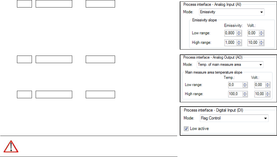
2.5.2. Process Interface (PIF)
Using Tools, Configuration and Device PIF menu you can activate
the Process interface (AI) as an input. The emissivity, ambient
temperature value and reference temperature can be scaled between
0 -10 V. For the other options you need to define a voltage value as a
Threshold [V] – the option is activated if the value is above this
threshold. If the box is tagged the threshold value below will activate
the action.
Using Tools, Configuration and Device PIF menu you can activate
the Process interface (AO) as an output. The chosen mode will be
scaled between 0 -10 V or the status of the mode will be set by
thresholds.
Using Tools, Configuration and Device PIF menu you can activate
the Process interface (DI). The mode will be defined by the voltage
signal. If Low active is untagged the mode will be initiated by the
upper voltage signal. If Low active is chosen the mode will be initiated
by the low voltage signal.
Note
You can use the process interfaces AI, AO and DI
simultaneously.