
Troubleshooting guide


MAGNUM VERSION 8 MANUAL REVISION 3.1
99
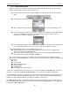
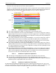
Setpoints 1 (chilled water target), 2 (plus dead band) & 3 (negative dead band) are used in this determination.
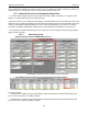
Setpoint #2×3 46.5°F
Setpoint #2×2 46.0°F
Setpoint #2 45.5°F
Setpoint #1 45.0°F
Setpoint #3 44.5°F
Setpoint #3×2 44.0°F
Setpoint #3×3 43.5°F
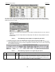
Example Setpoint Values:
# Name Value Time(sec)
1 Control Target 44.0
2 Control Zone + .5 0
3 Control Zone - .5 0
The zone boundaries can be increased by using the ‘Time(sec)’ field as a multiplier (Setpoint #2 for positive and
Setpoint #3 for negative boundaries). If this value is a 0 or 1 then the multiplier will be an assumed 1. In the example
above, if the ‘Time(sec)’ field was set to 2, then the differential between zones would be 1.0°F instead of 0.5°F; if set to
3, then the zone differential would be 1.5°F, etc.
Once the chilled water temperature is within the stable zone the CLLC will control the CLLC valve to maintain the
condenser liquid level. Once the system is considered stable it will remain in this condition unless the chilled water
temperature raises or drops into the unstable zones.
CLLC Control Logic
7.78.9.
The CLLC can be in one of the following three states:
1) CLLC OFF in this state the compressor is off. The CLLC will drive the valve to 100.0% and then hold. There is no
control in this state.
2) CLLC UNSTABLE in this state the compressor is on but the chilled water is not with in an acceptable temperature
range. Refer to section on CLLC Determining Stable or Unstable Condition.
In this state the purpose of the CLLC is to position the valve to create a liquid seal so that the chiller can generate
lift and pull the water temperature within the acceptable range.
If the liquid level is above the value in set point #216, the CLLC valve setting will remain at its present position. The
valve state will be VALVE HOLD.
If the liquid level is less than the value in set point #216, the CLLC valve setting will be closed until its opening is
equal to the value of set point #217, once this is reached the valve state will be VALVE HOLD. The CLLC will not
leave this state until the chilled water temperature returns to acceptable level or the compressor is turned off.
3) CLLC STABLE in this state the compressor is on and the chilled water is with in an acceptable temperature
range. Refer to section on CLLC Determining Stable or Unstable Condition.
In this state the purpose of the CLLC is to position the valve to create a sub-cooler level to get the efficiency out of
the chiller and not to control the valve within a couple percent of the actual set point. As long as the condenser
Control Zone
Stable Zone
Unstable Zone
Unstable Zone
Control temperature
must enter this zone to
switch from UNSTABLE
to STABLE
Control temperature
must enter either of
these red zones to
switch from STABLE
to UNSTABLE
Target
Stable Zone
Hysteresis Zone
Hysteresis Zone