
Troubleshooting guide


MAGNUM VERSION 8 MANUAL REVISION 3.1
97
# Name
Typical
Value
Description
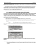
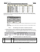
217 CLLC VALVE TRG 50.0
30
10
50
The ‘Value’ is the target or minimum opening of the CLLC control valve.
The ‘Time(sec)’ contains the normal delay between making valve adjustments.
This time is expressed in seconds.
The ‘Sec. to Ignore Safety’ contains the delay between making valve
adjustments when the CLLC is in a startup mode or the chilled water is not
with in its control zone, this is an unstable condition.
The ‘Window to extend Safety Time(sec)’ contains the maximum valve
adjustment value. This value has an assumed decimal place; that is a value
of 50 will allow a maximum adjustment of 5.0. The actual adjustment will be
calculated based upon the valve setting and its desired position.
This set point is only used if the AO TYPE of CLLC valve has been selected.
218 CLLC MAX ROC 2.5 The ‘Value’ contains the rate of change that will determine if the condenser
liquid level rate of change is moving fast enough
CLLC States
7.78.4.
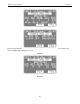
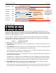
The CLLC states indicate the status of the CLLC unit. They can be viewed either from the Magnum’s status screen,
screen will follow the compressor information or from the MCS Connect status screen.
CLLC OFF: in this state there are no compressors on. The CLLC valve will be move to 100% open.
CLLC UNSTABLE: in this state a compressor is running but it either in startup mode or the chilled water
temperature is not within an acceptable range. The CLLC valve is not being controlled to provide the target
level of the condenser liquid but to provide a liquid seal to enable the compressor to generate lift. This state
will be entered whenever the chilled water temperature is not within an acceptable range. Refer to section on
CLLC Determining Stable or Unstable Condition.
CLLC STABLE: in this state a compressor is running but and the chilled water temperature is within an
acceptable range. The CLLC valve will be modulated to maintain the condenser liquid level within the target
control zone as defined by set point #216. Refer to section on CLLC Determining Stable or Unstable
Condition.
CLLC Valve States
7.78.5.
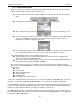
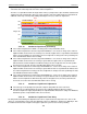
The CLLC valve states indicate the status of the CLLC valve. They can be view either from the Magnums status
screen, screen will follow the compressor information or from the MCS Connect status screen. The (XX) will contain
either (AO) or (RO) indicating the type of valve control that has been selected.
VALVE OPENING (XX): The unit is in an unstable state and valve is being opened.
VALVE CLOSING (XX): The unit is in an unstable state and valve is being closed.
VALVE HOLDING (XX): The unit is in an unstable state and valve not being changed.
ZONE 1 VLV HOLDG (XX): The unit is stable and the condenser liquid level is in ZONE 1 which requires no valve
positioning.
ZONE 2 VLV HOLDG (XX): The unit is stable and the condenser liquid level is in ZONE 2 and the valve position is
not being changed as the condenser liquid level rate of change is decreasing at an acceptable rate.
ZONE 2 VLV OPENG (XX): The unit is stable and the condenser liquid level is in ZONE 2 above the target
opening and the liquid level rate of change is not decreasing at an acceptable rate; therefore, the valve must be
opened.
ZONE 2 VLV CLOSG (XX): The unit is stable and the condenser liquid level is in ZONE 2 below the target
opening and the liquid level rate of change is not increasing at an acceptable rate; therefore, the valve must be
closed.
ZONE 3 VLV HOLDG (XX): The unit is stable and the condenser liquid level is in ZONE 3 and the valve position is
not being changed as the condenser liquid level rate of change is decreasing at an acceptable rate.
ZONE 3 VLV OPENG (XX): The unit is stable and the condenser liquid level is in ZONE 3 above the target
opening and the liquid level rate of change is not decreasing at an acceptable rate; therefore, the valve must be
opened.