
Troubleshooting guide


MAGNUM VERSION 8 MANUAL REVISION 3.1
96
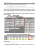
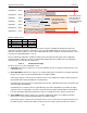
The relays must be set up as Pulse Relay type and the Pulse on Time (in tenth of second) and the Delay Between
Pulse (in seconds) columns must be setup. Suggest the initial values are Pulse on Time of 5 (.5 seconds) and Delay
Between Pulse of 2 (2 seconds).
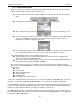
3) AO Type selected.
Condenser Level: select from a drop down list of sensor inputs. This will provide the level of the condenser
liquid level.
Valve Actuator: select from a drop down list of analog outputs. This will be the analog output that controls
the CLLC valve.
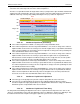
The following sensor inputs are required by the CLLC
7.78.2.
1) A CLLC Level sensor – This sensor will indicate the level percentage of Condenser Liquid Level.
2) CLLC Relay Output Position sensor – This sensor is required of the valve type is RO. This sensor will indicate
valve position. It may be necessary to develop an appropriate calculation for this sensor to read correctly using
the User Defined sensor type.
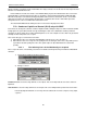
The following Setpoints are required by the CLLC
7.78.3.
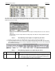
# Name
Typical
Value
Description
216 CLLC LEVEL TRG 60.0
5
The ‘Value’ is the target that is to be maintained of the condenser liquid level.
The ‘Time(sec)’ contains the dead band of the target. For example if the value is
60.0 (target) and the ‘Time(sec)’ field is 5 (dead band) the control zone for
the condenser liquid level is between 55.0 and 65.0.