
Troubleshooting guide


MAGNUM VERSION 8 MANUAL REVISION 3.1
95
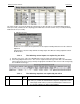
However if Flow A indicates that there is flow then circuits 1 and 3 will be in a ready to run state and Flow B
indicates that there is flow then circuits 2 and 4 will be in a ready to run state. The circuit states are based upon the flow
indicators associated with that circuit.
If Flow A indicates no flow, then circuits 1 and 3 will immediately be placed in a disabled state due to no flow, the
lead pump will be Locked Out after the time delay as stated in the ‘Value’ field in Setpoint #105 “PUMP FAILURE”.
When the lead pump is Locked Out the backup pump will be started. If flow is returned, then circuits 1 and 3 will be
allowed to run. If flow is not returned and the backup pump is Locked Out, then circuits 1 and 3 will be placed in a
Safety Off state. The same is true with Flow B and circuits 2 and 4.
The unit and all individual circuits will be placed in a Lockout state if all pumps have failed.
7.78. Condenser Liquid Level Control (CLLC) only with CENT
CLLC has been developed to control the condenser liquid level with centrifugal compressors. When activated via MCS
Config options the system will control the level by determining the status of the chilled water and then position the
opening of the CLLC control valve to either maintain liquid level or to create a liquid seal so the chiller can generate lift
and drop the water temperature to its set point.
There can be two types of control of the CLLC valve.
1) AO TYPE, the valve uses an analog output that will be varied to open or close the valve; or
2) RO TYPE, the valve uses 2 relays one for opening and one for closing the valve. These relays will be pulsed
to provide the desired opening of the valve. This option requires an input that indicates the actual valve
opening.
The following items in the MCS Config are required
7.78.1.
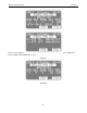
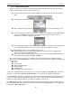
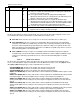
Base set up for the CLLC. The following section has been added to the Evaporator Info panel under the MAG CENT
V8 button:
1) No Condenser Liquid Level Control selected.
2) RO Type selected.
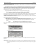
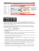
Condenser Level: select from a drop down list of sensor inputs. This sensor will provide the level of the condenser
liquid level.
Valve Position: select from a drop down list of sensor inputs. This sensor will provide the position of the CLLC valve.
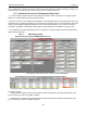
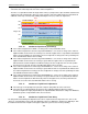
In the Relay Output Information screen 2 relays must be added at the end of the compressor relay output
sequence: