
Troubleshooting guide

MAGNUM VERSION 8 MANUAL REVISION 3.1
89
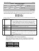
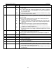
# Name
Typical
Value
Description
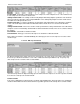
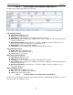
159 B-VFD DELAY 30
500
1000
The time delay expressed as seconds between making decisions as to pump
VFD setting.
‘Sec. to Ignore Safety’ field: contains the minimum valve setting. For example if
this cell contains 500, the valve will initially be set to 50.0% and it will never
be less than this value.
‘Window to extend Safety Time(sec)’ field: contains the maximum valve setting.
This will normally be 1000 for 100.0%.
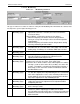
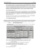
160 B-VFD TARGET 60.0
120
30
25
30
The target flow that is to be maintained. This can be a differential if both input
and output pressures sensors are specified or the actual flow of the input if only
sensor specified.
‘Time(sec)’ field: contains the delay in seconds before another pump can be
turned on once the valve gets to 100.0%
‘Sec. to Ignore Safety’ field: contains high dead band for the control zone. This
is added to the value of this set point. In this example the high dead band
will be 63.0.
‘Window to extend Safety Time(sec)’ field: contains low dead band for the
control zone. This is subtracted from the value of this set point. In this
example the low dead band will be 57.5.
‘Safety Time Extension’ field: contains the maximum valve adjustment that can
be made at one time. In this example the maximum adjustment to the valve
will be 3.0%..
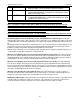
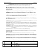
161 B-PUMP FLT 0
30
The ‘Value’ is not used as this set point is set up to check the status of a digital
input indicated in the Starting Pump Fault cell.
‘Time(sec)’ field: contains the delay before the system will place a pump in a
failed state.
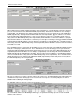
162 NO USED
163 B-HEAT TRGT 180.0 The heating target that is to be maintained.
164 B-HEAT ZONE+ 3.0 The high dead band for the heating control zone. This value is added to the
value of set point #163.
165 B-HEAT ZONE- 3.0 The low dead band for the heating control zone. This value is subtracted form
the value of set point #163.
189 B-FLA PUMP 30.0 The expended amp draw of the pump. If active this value is used to calculate
the high and the low ampere safeties limits. Refer to set points 75 and 76.
190 B-FLA BOILER 120.0 The ‘Value’ is not used as this set point is set up to check the status of a digital
input indicated in the Starting Boiler Fault cell.
‘Time(sec)’ field: contains the delay before the system will place a boiler stage
in a failed state.