
Troubleshooting guide

MAGNUM VERSION 8 MANUAL REVISION 3.1
83
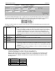
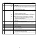
For Common VFD Fan Condensers with Bypass: Time in seconds
before the bypass can be used when a fault has occurred.
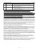
193 CND HI/LO ZONE The value in this Setpoint is the high and low zone for your target of
Setpoint #50 “CND TRGT“. If inactive then a default zone of 5 psi
will be used, if metric .3 Bar.
194 CND 2
ND
ZONE The value in this Setpoint is the 2nd high and low zone for your target
of Setpoint #50 “CND TRGT“. If inactive then a default zone of 20
psi will be used, if metric 1.4 Bar.
Note 1: The purpose of Setpoint #193 ‘CND HI/LO ZONE’ and the delays in the MAX AND MIN VFD Opening
cells for Setpoint #48 ‘CND ADJ DELAY’ are to prevent repeated cycling of additional stages.
Note 2: The purpose of Setpoint #194 ‘CND 2
nd
ZONE’ is to prevent the discharge pressure from over
shooting the target (Setpoint #50 ‘CND TARG’). The way the logic works is if the discharge pressure is in the
2
nd
Zone and the pressure is falling less than twice the CND ROC- (Setpoint #53 ‘CND ROC-‘) then a negative
adjustment will be made to the AO. If the discharge pressure is raising more than twice the rate of change
(Setpoint #53) then a positive adjustment will be made to the AO.
Note 3: The value in the “AO Starting Stage” cell under the MAG HVAC screen in the condenser info section
is the stage that has to be turned on to begin modulating the AO.
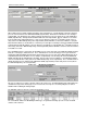
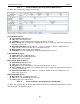
The following applies to both the modulating common and individual water condenser types: The ‘Default
Valve Opening % when Comp. is OFF’ cell can be used to set the valve (1) to be completely closed (0%), (2) the value
of Setpoint #52 (Valve % defined by Setpoint #52), or (3) completely open (100% if the Run/Stop indicator = ON else =
0%).
The delay timer will be decremented by a standard value of 1 every second, however if the control discharge pressure
is more than 15.0 psi (1.5 bar) away from the target Setpoint #50, then the delay will be decremented by 2; if more
than20.0 psi (2.0 bar) away from the target then the delay will be decremented by 4.
When the delay counts down to zero, an adjustment will be made based on the equation: (Control discharge pressure
– Setpoint #50) × Setpoint #54 ÷ Setpoint #51 = Adjustment Value.
When the control discharge pressure is greater than Setpoint #50 plus 5.0 psi (.5 bar) : If the control discharge
pressure rate of change is dropping too fast (more than twice the value of Setpoint #53), then close the valve by the
calculated adjustment. If the control discharge pressure rate of change is dropping too slowly (more than the value of
Setpoint #53), then open the valve by the calculated adjustment. Else make no adjustment.
When the control discharge pressure is less than Setpoint #50 minus 5.0 psi (.5 bar): If the control discharge
pressure rate of change is increasing too fast (more than twice the value of Setpoint #53) and the control discharge
pressure is greater than Setpoint #50 minus 20.0 psi (1.3 bar), then close the valve by the calculated adjustment. If the
control discharge pressure rate of change is increasing too slowly (more than the value of Setpoint #53), then open the
valve by the calculated adjustment. Else make no adjustment.
When the control discharge pressure is within the zone: If the control discharge pressure rate of change is
increasing more than the value of Setpoint #53, then close the valve by 1 percent. If the control discharge pressure
change is decreasing more than the value of Setpoint #53, then open the valve by 1 percent.
Modulating Condenser Type: If heat pump and the mode is HEAT (not in defrost) all condenser relays will be turned
on and the VFD set to 100% when compressor is turned on. If the control pressure is above the control zone, the
condenser will unload; if below the control zone the condenser will load else there will be no change.