
Troubleshooting guide
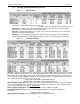


MAGNUM VERSION 8 MANUAL REVISION 3.1
80
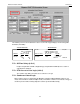
7.74.3.6. RO Step Common with a Fan AO and Condenser Faults
The above example is the same as the previous example with the addition of a Fan AO and two condenser faults.
Fan AO Control (same for all types of air condenser control)
Two more Setpoints than the previous example are needed to control the speed of the fan:
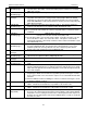
Setpoint # Name Value
54 CND MIN SPD 20.0%
55 CND MAX SPD 100.0%
CND FAN 1 will be turned on when the control pressure is equal to or greater than 200.0, same as in previous
example. At this point the Fan AO speed will be set to its maximum value, Setpoint #55. If the pressure changes
between 170.0 and 214.9 the fan speed will also be modulated proportionally between its maximum and minimum
settings. If the pressure is at 185.0 the fan speed will be set to 61.2%. If the pressure is at 190.0 the fan speed will
increase to 75.0%. This will provide precision control in maintaining optimum discharge pressure.
If the pressure increases to 215.0 the condenser’s second stage will be turned on and the fan speed will also be at
100.0%. If the pressure changes between 175.0 and 229.9 the fan speed will also be modulated proportionally
between its maximum and minimum settings.
If the pressure increases to 230.0 the condenser’s third stage will be turned on and the fan speed will also be at
100.0%. If the pressure changes between 180.0 and 229.9 the fan speed will also be modulated proportionally
between its maximum and minimum settings. If the pressure is at 230.0 and above the fan speed will be at 100.0%.
As the pressure decreases toward the Cut Out point the fan speed will decrease toward its minimum setting. Once a
stage is turned off, the fan speed will be set to 100.0% and again it will be modulated based upon the pressure.
Condenser Faults
This example has two condenser faults. They must be consecutive digital input types starting with FAN FLT 1. If either
of these digital inputs are ON for the time specified in Setpoint #90 if active, then the unit will be locked out and an
alarm message will be generated.
7.74.3.7. RO Step Individual
The RO Step Individual has a bank of fans for each compressor. The number and location of the fan are specified
under the Circuit Base screen.