
Troubleshooting guide


MAGNUM VERSION 8 MANUAL REVISION 3.1
58
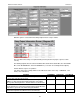
(Setpoint #123) to 10.0%. The economizer valve opening will be increased by this amount if the
temperature control rate of change is greater than the value of Setpoint #27. With Setpoint #126 equal to 2
and #127 equal to 1, the valve will be adjusted by 2% for every degree difference from the target.
The economizer function will wait 30 seconds (Setpoint #124) before calculating the next adjustment. If the
control temperature is now 47.3F the following adjustment will be made.
47.3 – 44.0 = 3.3 x 2 / 1 = 6.6. Since this is less than 10.0 the valve will be open an additional 6.6% if the
temperature control rate of change is greater than the value of Setpoint #27.
Each adjustment will be made after a delay of 30 seconds. If the control temperature is below the control
target (Setpoint #1) and above the bottom the control zone (43.0F to 44.0F) there will be no change to
valve opening.
If the control temperature drops below the control zone the valve opening will be reduced. For example if
the control temperature is 42.6F then the following calculation will be made:
42.6 – 44.0 = 1.4 x 2 / 1 = 2.8. Since this is less than 10.0 the valve opening will be reduced an additional
2.8%.
When the valve reaches its maximum opening of 100.0% (Setpoint #122) the economizer function will use
other fans if they are available. In this example there are no fans that are associated only with economizer
but the condenser fans can now be used. After the time delay of 120 seconds (Setpoint #125) the first
condenser fan will be turned on (the first fan of the first compressor unless unavailable).
At this point the unit state is ECONOMIZER ONLY, the economizer valve is at 100%, and the compressor
fans will be used to aid in the economizer cooling. The delay between starting the condenser fans will be
30 seconds (Setpoint #124). If all condenser fans are available and not manually turned off, the pattern of
starting fans will be the first fan on compressor 1, after the delay then the first fan of compressor 2, after the
delay then the second fan on compressor 1. This will continue until all available condenser fans have been
turned on.
Once all of the condenser fans have been turned on there will be a delay of 240 seconds (Setpoint #107).
At this time the Unit State will be changed and mechanical cooling will be enabled. When a compressor is
running, its associated condenser fans will be controlled by the discharge pressure of the running
compressors.
7.41. High Suction Superheat Safety
To add a high suction superheat safety, make Setpoint #203 “HiSuctSheat” active. If the suction
superheat is greater than the value of this Setpoint for the ‘Time(sec)’ field, an alarm will be
generated and the compressor will be shut down with a safety or Lockout state.
7.42. Low Temperature Safety and Unload (Low Saturated Suction
Temperature)
The Magnum is set up to check for low refrigerant temperature safety and unload functions. To
enable this test make Setpoint #155 “LO REF TMP” active and point to the sensor in the
‘Refrigeration Temp’ column of the Compressor SI grid in MCS-Config.
This safety will be checked only when the compressor is running. If the sensor value is less than
Setpoint #155 for the ‘Time(sec)’ field, then an alarm message will be generated and the associated
compressor will either be placed in a safety or Lockout state.
The Magnum will also determine if a low temperature condition occurs and to stop loading or unload
if necessary. If the sensor value is less than the value of Setpoint #155 plus Setpoint #156 “LO REF
UNLD”, then the compressor state will be LO TMP UNLOAD. Refer to state (21) in section 6.2.26.
By using the User Logic type sensor, we can test any value for a low condition. For example point the
refrigerant temperature index to a User Logic sensor that picks up the saturated suction temperature for