
Troubleshooting guide


MAGNUM VERSION 8 MANUAL REVISION 3.1
45
7.15. Hot Gas Bypass
Control of the Hot Gas Bypass function will depend on which Setpoints are made active/inactive. Refer to
section 13 Setpoints #4-#7.
Setpoints #4-#7 INACTIVE - If Setpoints #4-#7 are all inactive, then the HGB is enabled when the
machine is unloaded to within 25% of the minimum slide percentage. The HGB is disabled when the
machine rises above 30% of the minimum slide percentage. (These are just default values that can be
overridden in the “Time(sec)” fields of Setpoints #4 and #5. The “Time(sec)” field of Setpoint #4 contains
the minimum slide percentage offset to enable the HGB; the “Time(sec)” field of Setpoint #5 contains the
minimum slide percentage offset to disable the HGB. For example, if Setpoint #4 “Time(sec)” field has a
value of 10 and Setpoint #5’s is15, then the HGB will enable when the compressors FLA% is within 10%
of Setpoint #31 “MIN FLA%” and will disable when FLA% goes above 15%.)
Only Setpoints #4-#5 ACTIVE - The HGB is on when the machine is unloaded and the leaving liquid
goes below the Cut In (Setpoint #4 “HGS TEMP ON”). HGB is turned off when the leaving liquid
temperature goes above the Cut Out (Setpoint #5 “HGS TEMP OFF”) or the machine leaves the
unloaded state.
Only Setpoints #6-#7 ACTIVE- The HGB is on when the machine is unloaded and the suction pressure
goes below the Cut In (Setpoint #6 “HGS PSI ON”). HGB is turned off when the suction pressure goes
above the Cut Out (Setpoint #7 “HGS PSI OFF”) or the machine leaves the unloaded state.
Setpoints #4-#7 ACTIVE - If both groups of Setpoints are active, then the HGB is on when the machine
is unloaded and either the leaving liquid temperature or the suction pressure goes below the respective
Cut In limit. The HGB goes off when the machine leaves the unloaded state or both the leaving liquid
temperature and the suction pressure goes above the respective Cut Out limits.
7.16. Chilled Water Reset
Chilled Water Reset (CWR) is a 0 to 5 volts dc Sensor Input (Display Type is TRGTRST) to the MCS
microprocessor. The CWR follows the following rules using Setpoint #21 “MAX TRG RESET”:
1. If the input is 2.5 volts dc the CWR is zero.
2. At 0 vdc the CWR is a negative value equal to the Setpoint value.
3. At 5 vdc the CWR is a positive value equal to the value in the Setpoint.
4. For values in between 0 – 2.5 and 2.5 – 5.0 the CWR is a plus or minus value which is proportional to
the Sensor Input voltage.
7.17. Oil Equalization Option
Oil equalization occurs with common suction/discharge systems. This feature allows for oil to
equalize between compressors by opening a solenoid valve. The oil equalization occurs at
compressor startup. Refer to section 12 for Relay Output order and options. If this feature is
specified in the Circuit Base screen, the micro will energize the Oil Equalization solenoid valve
for 1 minute at compressor startup.
7.18. Liquid Injection Option
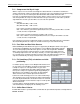
This option is specified in the Circuit Base screen:
In the Liquid Injection column there is a dropdown menu for each compressor, giving options of No Liquid
Injection, 1 Stage, or 2 Stage. If 2 Stage option is selected, the second stage relay must follow the list of