
Troubleshooting guide


MAGNUM VERSION 8 MANUAL REVISION 3.1
44
7.11. Compressor Anti-Cycle Logic
When a compressor is to be turned off, the Magnum software will make a calculation to determine the
amount of time that the compressor will remain in an anti-cycle state. This calculation is based upon how long
the compressor has been on and Setpoints #59 “ACYC OFF->ON” and #63 “ACYC ON->ON”.
If the value of Setpoint #63 minus the amount of time that the compressor has been on is greater than the
value in Setpoint #59, the compressor will remain in the anti-cycle state for the period of time specified in
Setpoint #63. Else the anti-cycle timer will be set to the value in Setpoint #59.
For example:
#59 (ANTI-CYC OFF) = 300 seconds
#63 (ANTI-CYC ON) = 600 seconds
If the compressor had been running for 3 minutes (180 seconds)
600 – 180 = 420 this is greater than Setpoint #59; therefore, the anti-cycle timer will be set to 600
seconds, the value of Setpoint #63.
If the compressor had been running for 12 minutes (720 seconds)
600 – 720 = -120 this is less than Setpoint #59; therefore, the anti-cycle timer will be set to 300
seconds, the value of Setpoint #59.
If the controller loses power, the length of time that the system was down will be taken into consideration
when determining whether the compressor should be in an anti-cycle state and for how long.
7.12. Part Wind and Star Delta Starters
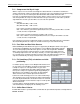
Both Part Winding and Star Delta starter types are supported by the Magnum software. This option is
specified in the ‘Part Winding’ cell of the Circuit Base screen in MCS-Config and will require two
successive Relay Output points. When this option is selected, make Setpoint #73 “STARTER
DLAY” active. This Setpoint contains the delay in seconds or transition percentage before the
second Relay Output is turned on. This delay is normally 1 second for part winding or 5 seconds
for a star delta starter. If using the transition percentage option, after initial startup amp spike, the
amps must fall below this percentage of the FLA for the second step to be turned on.
7.13. Full Load Amp (FLA) calculation and slide
positioning
For variable capacity compressors the Magnum will calculate a FLA
for each compressor and it will be stored in the FLA Setpoints (#171
to #190) for compressors 1 through 20 with every pass of the
algorithm. The calculated FLA value will be displayed when viewing
the respective compressor Setpoint through the Keypad/Display or
MCS-Connect. The calculation is based upon the slide multiplier,
divisor and offset values and then adjusted for the difference
between the actual and design pressures for suction and discharge.
This calculation is then used to determine the slide position by taking
the actual amp draw divided the calculated FLA value. The load and
unload solenoids will be used to match the compressor slide position
with the wanted FLA.
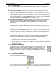
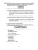
If a FLA Setpoint is changed from MCS Connect both the original
and calculated values are displayed in the following screen:
7.14. Chiller Barrel Heater
If a Chiller Barrel Heater is specified, it will be controlled based upon ambient temperature and Setpoint #134
“BARREL HEATER“.