
Troubleshooting guide


MAGNUM VERSION 8 MANUAL REVISION 3.1
43
Setpoint can be manually changed to force a different compressor as the lead compressor or to enable auto
rotation.
When this option is enabled, the Magnum will rotate the compressors based upon the value in Setpoint # 104
“CMP ROTATION”
If Setpoint # 104 is zero, rotation will occur with every complete capacity cycle and the next
compressor will be selected as the lead compressor.
If Setpoint # 104 is nonzero, the value is the number of days between rotations. At midnight the
Magnum will check if it is time to rotate compressors. If yes, the Magnum will check the run hours on
each compressor and select the one with the least amount of run hours to be the lead compressor.
If Setpoint # 104 is set up as an ALARM Setpoint type, a compressor rotation message will be generated
each time a compressor is rotated.
7.10. Custom Rotation
The requirement is to enable rotation only in the first barrel and do not turn ON any compressors associated
with the second barrel until all compressors are ON in the first barrel. When decreasing refrigerant capacity, if
any compressors in the second barrel are ON, they must first be turned OFF before turning OFF any
compressors in the first barrel. Only first ON and first OFF lead rotation strategy can be used.
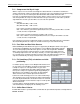
To activate this option Setpoint #103 “LEAD COMP” must be set up as follows:
Value: 0 (indicates auto rotation, must be 0)
Time (SEC): 0 (indicates first on first off, must be 0)
Select Value: DIGITAL/SW
Type of Setpoint: Target (must be Target type)
High Zone: 1 (this is the starting compressor following a reset; usually 1)
Low Zone: 1 (number to rotate, will default to 1)
Night Setback: 8 (number of compressors in the first barrel)
If the Value, Time, and Type cells are not set as indicated, normal rotation using Setpoints #103 “LEAD
COMP” and #104 “COMP ROTATION” will be used.
The following examples have 16 compressors, dual barrels with 8 compressors in each. Barrel 1 has
compressors 1 through 8 and 9 through 16 are in barrel 2. The wanted/actual ON will function as usual only
the rotation and the sequence of turning on the compressors have been changed.
Example 1: Compressor 1 is the lead capacity calls for 4 circuits to be ON (wanted 4/ actual 4), then reduced
to 0/0.
Compressors 1, 2, and 3, then 4 will be turned ON. As capacity is reduced, Compressor 1 will be
turned OFF and the lead will be rotated to Compressor 2. Then Compressors 2, 3, and 4 will be turned OFF
with the lead ending with Compressor 5.
Example 2: Compressor 5 is now the lead and capacity calls for 6 compressors to be ON (6/6) then reduce
to 0/0.
Compressors 5, 6, 7, and 8, then 1 and 2 will be turned ON (6/6). As capacity is reduced,
Compressors 5, 6, 7, and 8, then 1 and 2 will be turned OFF (0/0) and Compressor 3 will be the lead. Note,
compressors in barrel 2 were not turned ON.
Example 3: Compressor 3 is now the lead and capacity calls for 12 compressors to be ON (12/12) then
reduce to 0/0.
Compressors 3, 4, 5, 6, 7, and 8, then 1 and 2 will be turned ON (8/8). At this point all compressors in
barrel 1 are ON, as more capacity is needed Compressors 9 through 16 will be used. Compressors 9, 10, 11,
and 12 will be turned ON to reach 12/12. As capacity is reduced, Compressors 9 then 10, 11, and 12 will be
turned OFF (8/8) at this point. Now, all compressors in barrel 2 are OFF and all compressors in barrel 1 can
now be turned OFF if less capacity is needed. Compressor 3 followed by 4, 5, 6, 7, 8, and 1 then 2 will be
turned OFF (0/0). At this point Compressor 3 is the lead compressor.