
Troubleshooting guide


MAGNUM VERSION 8 MANUAL REVISION 3.1
33
changing, its direction, and its distance from the control zone will all be used to determine how the Magnum
will respond.
7.2.1.5. Step Delay and Sensitivity
The Magnum will not attempt to take action until the Step Delay counts down to zero. Setpoint #26 contains
the initial value. The speed that the counter will decrement by is based on the control input rate of change and
the sensitivity that has been specified in Setpoint #25. The purpose of the sensitivity value is to limit how
quickly the Magnum reacts to changes indicated by the control sensor. The lower the value of this Setpoint,
the faster the Magnum will react to changes of the control sensor.
7.3. Voltage Step Control Logic
An alternate control strategy is based on a variable voltage input to the Magnum board. The different stages of
capacity will Cut In or Out depending on the voltage input. This option is selected in the MAG V8 screen under
the Evaporator Info tab.
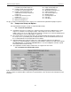
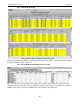
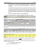
Setpoints #2-18 contain the Cut-In and Cut-Out voltage thresholds. The status screen has been changed to
show the actual voltage on the top line and to indicate voltage control on the bottom line. The step delay
between adjustments is based on Setpoint #26 “STEP DELAY”.
Note: Liquid Injection and EXV logic are both disabled when this option is used.
7.4. Variable Capacity Control Method
Screw Compressor with slide piston
7.4.1.
This option is specified in MCS-Config by selecting the compressor type in the Compressor
Information Panel under the MAG V8 screen.
As stated in the previous section, the control strategy is designed to modulate the system capacity to maintain
the control sensor reading within the specified control zone. The system capacity will be based upon the
number of compressors that are Wanted On. When the first, or an additional compressor, is turned on the
system capacity will be set to the calculated value. For the first compressor this will be the value of Setpoint
#31 “MIN FLA %”. When additional compressors are brought on, their capacity is calculated to provide the
same percentage of capacity prior to the change. The Magnum will adjust the required capacity between the
calculated and the maximum value an as specified in Setpoint #30 “MAX FLA %”. All compressors that are on
will be adjusted together to meet the system capacity.
When the maximum capacity value of the currently operating compressors has been reached, an additional
compressor, if available, will be Wanted On. The number of compressors Wanted On will be increased by one
and the system capacity will be set to the calculated value to maintain the same capacity as before the change
and the sequence will begin again. Once all available compressors are on, their maximum will be 100%
regardless of the value in Setpoint #30 “MAX FLA %”.
When the minimum calculated value has been reached, a compressor will be turned off. This will occur when
the reduced number of compressors can achieve the same capacity at 90%. The number of compressors
Wanted On will be decreased by one and the system capacity will be set to 90% and the sequence will begin
again.
The compressor slide control is based upon the amps drawn by that compressor. For example, if Setpoint #31
“MIN FLA %” is set to 30%, that means 30% of the calculated full load amperage for that compressor.
Screw compressors with slide pistons that are turned on can either be loading (load solenoids are pulsed),
unloading (unload solenoids are pulsed), or in a hold state (no action is taken). The state of each compressor
reflects this action.