
Troubleshooting guide


MAGNUM VERSION 8 MANUAL REVISION 3.1
32
7. Standard Control Options
The following options are specified in MCS-Config when building the configuration. These options are
used to customize the system to meet the individual control requirements.
7.1. General Options
Control method can be based upon the control zone or a voltage input indicating the number of
stages to be on.
The control temperature sensor can be either the returning or leaving sensor.
Electronic expansion valves make dynamic adjustments based on capacity changes.
Chilled water reset from the Building Management System (BMS).
Condenser control maintaining sufficient discharge superheat for good oil separation.
Evaporator pump control.
Anti-cycle timers (OFF to ON and ON to ON).
Maximum of 20 circuits per Magnum, with selectable compressor rotation.
Warning RO (turned on for low suction unload, high discharge unload, etc.).
Alarm RO (turned on whenever an alarm is generated).
Optional auto rotation for compressors.
Low and/or high ambient temperature shut down.
7.2. Magnum Control Zone Logic
The control strategy is designed to modulate the compressor(s) capacity to maintain the control sensor
reading within the specified control zone. To accomplish this, the Magnum will constantly monitor the control
value, its rate of change, and position in relationship to the control zone and make adjustments accordingly.
The strategies for a fixed step system, reciprocating compressor, reciprocating compressor with an inverter,
variable (slide) step system, or a screw compressor are all slightly different. The variable step system allows
for infinite variations of capacity while the fixed step system does not.
Common Definitions
7.2.1.
7.2.1.1. Target
The control target is specified in Setpoint #1. This will be the base of developing the control zone.
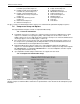
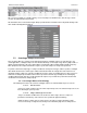
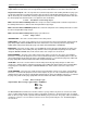
7.2.1.2. Control Zone
The control zone is developed by utilizing two more Setpoints to calculate the upper and lower limits. Setpoint
#2 is added to the target to determine the deadband to the upper limit, and Setpoint #3 is subtracted from the
target to determine the deadband to the lower limit.
Example: Setpoint #1 Target = 45
Setpoint #2 Upper Deadband = 1
Setpoint #3 Lower Deadband = 1
7.2.1.3. Control Sensor
This sensor has been specified in MCS-Config as providing the control value reading. It will normally be the
entering temperature, leaving temperature, or suction pressure. The Setpoints must be adjusted according to
the type of control measurement selected.
7.2.1.4. Control Input Rate of Change
The Rate of Change is how rapidly the control value changes over a set period of time. If the control value is
increasing, the rate will be positive; if it is decreasing, the rate will be a negative value. How quickly the input is
Control Zone + 1
Control Zone - 1
45
Temperature
Target
Control Zone
44
43
46
47
Upper Limit
Lower Limit